
Page 16: of Offshore Engineer Magazine (Dec/Jan 2013)
Read this page in Pdf, Flash or Html5 edition of Dec/Jan 2013 Offshore Engineer Magazine
 15
15
 17
17
FRONTIERS sections. A net small downward force is maintained with ballasting operations applicable in response to topsides weight changes of signifcance.
Paralleling the design aspects of deep water spars, the buoyant tower confgura- tion provides a center of buoyancy above its center of gravity and yields a hull
Self-installing tower scope unconditionally stable.
A key enabling attribute for the tower substructure is buoyancy and its avail- ofers production solution ability for a mid-water depth scope.
Compared to a conventional jacket/pile scope, buoyancy offers unique project execution fexibility.
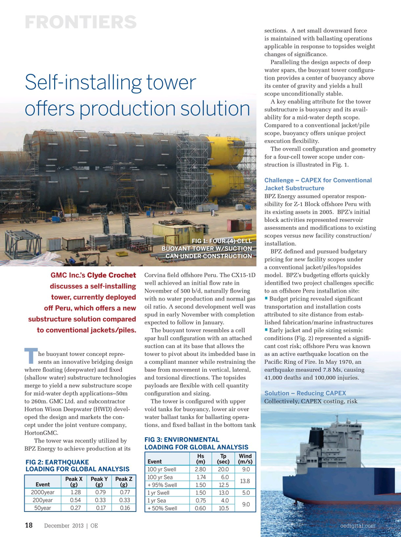
The overall confguration and geometry for a four-cell tower scope under con- struction is illustrated in Fig. 1.
Challenge – CAPEX for Conventional
Jacket Substructure
BPZ Energy assumed operator respon- sibility for Z-1 Block offshore Peru with its existing assets in 2005. BPZ’s initial block activities represented reservoir assessments and modifcations to existing scopes versus new facility construction/
FIG 1: FOUR (4) CELL installation.
BUOYANT TOWER W/SUCTION
BPZ defned and pursued budgetary
CAN UNDER CONSTRUCTION pricing for new facility scopes under a conventional jacket/piles/topsides
Corvina feld offshore Peru. The CX15-1D model. BPZ’s budgeting efforts quickly
GMC Inc.’s Clyde Crochet well achieved an initial fow rate in identifed two project challenges specifc discusses a self-installing
November of 500 b/d, naturally fowing to an offshore Peru installation site: tower, currently deployed • with no water production and normal gas Budget pricing revealed signifcant oil ratio. A second development well was transportation and installation costs of Peru, which ofers a new spud in early November with completion attributed to site distance from estab- substructure solution compared expected to follow in January. lished fabrication/marine infrastructures •
The buoyant tower resembles a cell Early jacket and pile sizing seismic to conventional jackets/piles.
spar hull confguration with an attached conditions (Fig. 2) represented a signif- suction can at its base that allows the cant cost risk; offshore Peru was known he buoyant tower concept repre- tower to pivot about its imbedded base in as an active earthquake location on the
T sents an innovative bridging design a compliant manner while restraining the Pacifc Ring of Fire. In May 1970, an where foating (deepwater) and fxed base from movement in vertical, lateral, earthquake measured 7.8 Ms, causing (shallow water) substructure technologies and torsional directions. The topsides 41,000 deaths and 100,000 injuries.
merge to yield a new substructure scope payloads are fexible with cell quantity
Solution – Reducing CAPEX for mid-water depth applications–50m confguration and sizing.
Collectively, CAPEX costing, risk to 260m. GMC Ltd. and subcontractor The tower is confgured with upper
Horton Wison Deepwater (HWD) devel- void tanks for buoyancy, lower air over oped the design and markets the con- water ballast tanks for ballasting opera- cept under the joint venture company, tions, and fxed ballast in the bottom tank
HortonGMC.
FIG 3: ENVIRONMENTAL The tower was recently utilized by
LOADING FOR GLOBAL ANALYSIS
BPZ Energy to achieve production at its
Hs Tp Wind
Event (m) (sec) (m/s)
FIG 2: EARTHQUAKE
LOADING FOR GLOBAL ANALYSIS 100 yr Swell2.80 20.09.0 100 yr Sea 1.74 6.0
Peak X Peak Y Peak Z 13.8 (g) (g) (g) Event + 95% Swell1.5012.5 2000year1.28 0.790.77 1 yr Swell 1.50 13.05.0 200year0.540.330.33 1 yr Sea 0.75 4.0 9.0 50year 0.270.170.16 + 50% Swell 0.6010.5
December 2013 | OE oedigital.com 18 018_OE1213_frontier1.indd 18 11/22/13 6:12 PM