
Page 17: of Offshore Engineer Magazine (Dec/Jan 2013)
Read this page in Pdf, Flash or Html5 edition of Dec/Jan 2013 Offshore Engineer Magazine
 16
16
 18
18
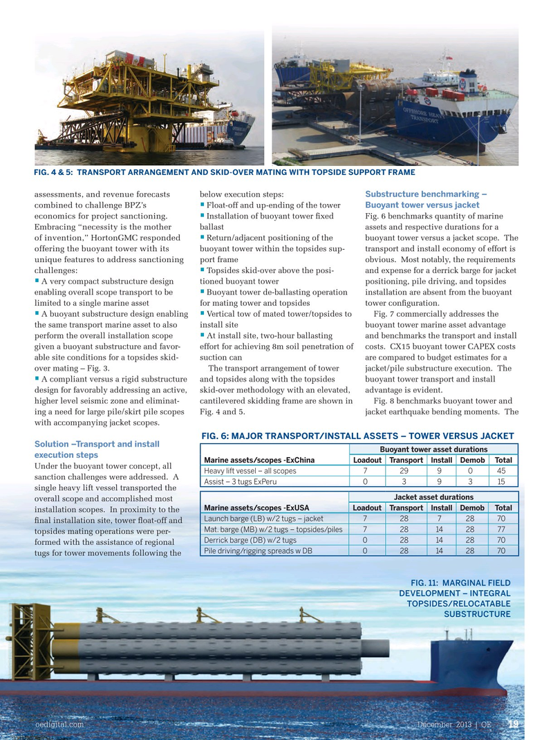
FIG. 4 & 5: TRANSPORT ARRANGEMENT AND SKID-OVER MATING WITH TOPSIDE SUPPORT FRAME
Substructure benchmarking – assessments, and revenue forecasts below execution steps:
Buoyant tower versus jacket • Float-off and up-ending of the tower combined to challenge BPZ’s • Installation of buoyant tower fxed Fig. 6 benchmarks quantity of marine economics for project sanctioning. ballast assets and respective durations for a
Embracing “necessity is the mother • Return/adjacent positioning of the buoyant tower versus a jacket scope. The of invention,” HortonGMC responded buoyant tower within the topsides sup- transport and install economy of effort is offering the buoyant tower with its port frame obvious. Most notably, the requirements unique features to address sanctioning • Topsides skid-over above the posi- and expense for a derrick barge for jacket challenges: • A very compact substructure design tioned buoyant tower positioning, pile driving, and topsides • enabling overall scope transport to be Buoyant tower de-ballasting operation installation are absent from the buoyant limited to a single marine asset for mating tower and topsides tower confguration.
• • A buoyant substructure design enabling Vertical tow of mated tower/topsides to Fig. 7 commercially addresses the the same transport marine asset to also install site buoyant tower marine asset advantage • perform the overall installation scope At install site, two-hour ballasting and benchmarks the transport and install given a buoyant substructure and favor- effort for achieving 8m soil penetration of costs. CX15 buoyant tower CAPEX costs able site conditions for a topsides skid- suction can are compared to budget estimates for a over mating – Fig. 3. The transport arrangement of tower jacket/pile substructure execution. The • A compliant versus a rigid substructure and topsides along with the topsides buoyant tower transport and install design for favorably addressing an active, skid-over methodology with an elevated, advantage is evident. higher level seismic zone and eliminat- cantilevered skidding frame are shown in Fig. 8 benchmarks buoyant tower and ing a need for large pile/skirt pile scopes Fig. 4 and 5. jacket earthquake bending moments. The with accompanying jacket scopes.
FIG. 6: MAJOR TRANSPORT/INSTALL ASSETS – TOWER VERSUS JACKET
Solution –Transport and install
Buoyant tower asset durations execution steps
Marine assets/scopes -ExChina Loadout Transport Install DemobTotal
Under the buoyant tower concept, all
Heavy lift vessel – all scopes 7299045 sanction challenges were addressed. A
Assist – 3 tugs ExPeru 039315 single heavy lift vessel transported the
Jacket asset durations overall scope and accomplished most
Marine assets/scopes -ExUSA Loadout Transport Install Demob Total installation scopes. In proximity to the
Launch barge (LB) w/2 tugs – jacket 728728 70 fnal installation site, tower foat-off and
Mat. barge (MB) w/2 tugs – topsides/piles728 14 28 77 topsides mating operations were per-
Derrick barge (DB) w/2 tugs 028 14 28 70 formed with the assistance of regional
Pile driving/rigging spreads w DB 028 14 28 70 tugs for tower movements following the
FIG. 11: MARGINAL FIELD
DEVELOPMENT – INTEGRAL
TOPSIDES/RELOCATABLE
SUBSTRUCTURE oedigital.com December 2013 | OE 19 018_OE1213_frontier1.indd 19 11/22/13 6:12 PM