
Page 18: of Offshore Engineer Magazine (Dec/Jan 2013)
Read this page in Pdf, Flash or Html5 edition of Dec/Jan 2013 Offshore Engineer Magazine
 17
17
 19
19
FRONTIERS
FIG. 8: BUOYANT TOWER AND
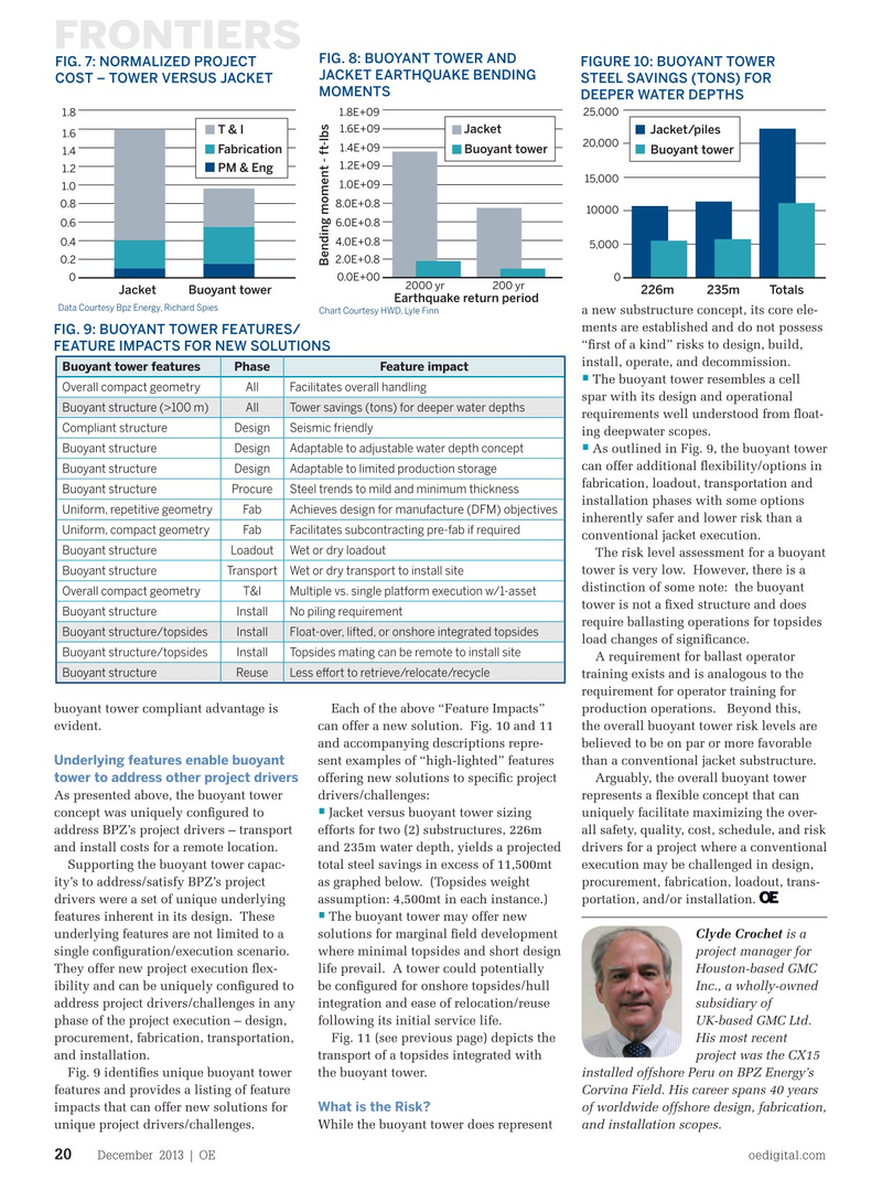
FIG. 7: NORMALIZED PROJECT FIGURE 10: BUOYANT TOWER
JACKET EARTHQUAKE BENDING
COST – TOWER VERSUS JACKET STEEL SAVINGS (TONS) FOR
MOMENTS
DEEPER WATER DEPTHS 1.8 1.8E+09 25,000 1.6E+09
T & I Jacket Jacket/piles 1.6 20,000 1.4E+09
Fabrication Buoyant tower Buoyant tower 1.4 1.2E+09
PM & Eng 1.2 15,000 1.0E+09 1.0 0.8 8.0E+0.8 10000 0.6 6.0E+0.8 0.4 4.0E+0.8 5,000 0.2 2.0E+0.8
Bending moment - ft-lbs 0 0.0E+00 0 2000 yr200 yr
JacketBuoyant tower 226m235mTotals
Earthquake return period
Data Courtesy Bpz Energy, Richard Spies
Chart Courtesy HWD, Lyle Finn a new substructure concept, its core ele- ments are established and do not possess
FIG. 9: BUOYANT TOWER FEATURES/ “frst of a kind” risks to design, build,
FEATURE IMPACTS FOR NEW SOLUTIONS install, operate, and decommission.
Buoyant tower featuresPhase Feature impact •
The buoyant tower resembles a cell
Overall compact geometryAllFacilitates overall handling spar with its design and operational
Buoyant structure (>100 m)AllTower savings (tons) for deeper water depths requirements well understood from foat-
Compliant structure DesignSeismic friendly ing deepwater scopes.
Buoyant structure DesignAdaptable to adjustable water depth concept • As outlined in Fig. 9, the buoyant tower can offer additional fexibility/options in
Buoyant structure DesignAdaptable to limited production storage fabrication, loadout, transportation and
Buoyant structure ProcureSteel trends to mild and minimum thickness installation phases with some options
Achieves design for manufacture (DFM) objectives
Uniform, repetitive geometry Fab inherently safer and lower risk than a
Uniform, compact geometry Fab Facilitates subcontracting pre-fab if required conventional jacket execution.
Buoyant structure LoadoutWet or dry loadout
The risk level assessment for a buoyant tower is very low. However, there is a
Buoyant structure TransportWet or dry transport to install site distinction of some note: the buoyant
Overall compact geometryT&IMultiple vs. single platform execution w/1-asset tower is not a fxed structure and does
Buoyant structure InstallNo piling requirement require ballasting operations for topsides
Buoyant structure/topsides InstallFloat-over, lifted, or onshore integrated topsides load changes of signifcance.
Buoyant structure/topsides InstallTopsides mating can be remote to install site
A requirement for ballast operator
Buoyant structure ReuseLess efort to retrieve/relocate/recycle training exists and is analogous to the requirement for operator training for
Each of the above “Feature Impacts” buoyant tower compliant advantage is production operations. Beyond this, can offer a new solution. Fig. 10 and 11 evident. the overall buoyant tower risk levels are and accompanying descriptions repre- believed to be on par or more favorable
Underlying features enable buoyant sent examples of “high-lighted” features than a conventional jacket substructure. tower to address other project drivers offering new solutions to specifc project Arguably, the overall buoyant tower drivers/challenges: As presented above, the buoyant tower represents a fexible concept that can •
Jacket versus buoyant tower sizing concept was uniquely confgured to uniquely facilitate maximizing the over- efforts for two (2) substructures, 226m address BPZ’s project drivers – transport all safety, quality, cost, schedule, and risk and 235m water depth, yields a projected and install costs for a remote location. drivers for a project where a conventional total steel savings in excess of 11,500mt Supporting the buoyant tower capac- execution may be challenged in design, as graphed below. (Topsides weight ity’s to address/satisfy BPZ’s project procurement, fabrication, loadout, trans- assumption: 4,500mt in each instance.) drivers were a set of unique underlying portation, and/or installation. • features inherent in its design. These The buoyant tower may offer new solutions for marginal feld development underlying features are not limited to a Clyde Crochet is a where minimal topsides and short design single confguration/execution scenario. project manager for life prevail. A tower could potentially They offer new project execution fex- Houston-based GMC be confgured for onshore topsides/hull ibility and can be uniquely confgured to Inc., a wholly-owned integration and ease of relocation/reuse address project drivers/challenges in any subsidiary of following its initial service life. phase of the project execution – design, UK-based GMC Ltd.
Fig. 11 (see previous page) depicts the procurement, fabrication, transportation, His most recent transport of a topsides integrated with and installation. project was the CX15 the buoyant tower. Fig. 9 identifes unique buoyant tower installed offshore Peru on BPZ Energy’s features and provides a listing of feature Corvina Field. His career spans 40 years
What is the Risk?
impacts that can offer new solutions for of worldwide offshore design, fabrication,
While the buoyant tower does represent unique project drivers/challenges. and installation scopes.
December 2013 | OE oedigital.com 20 018_OE1213_frontier1.indd 20 11/22/13 6:15 PM