
Page 46: of Offshore Engineer Magazine (Dec/Jan 2013)
Read this page in Pdf, Flash or Html5 edition of Dec/Jan 2013 Offshore Engineer Magazine
 45
45
 47
47
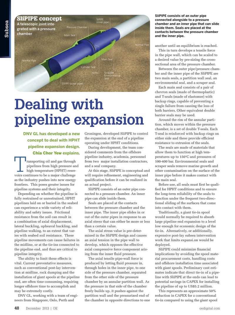
SliPIPE consists of an outer pipe
SliPIPE concept connected alongside to a pressure chamber and an inner pipe that can slide
A telescopic joint inte- inside them. Seals are placed at the grated with a pressure contacts between the pressure chamber chamber and the inner pipe.
Subsea another until an equilibrium is reached.
This in turn develops a tensile force in the pipe wall, which can be scaled to a desired value by pre-sizing the cross- sectional area of the pressure chamber.
Between the outer pipe/pressure cham- ber and the inner pipe of the SliPIPE are two main seals, a partition wall seal, an environmental seal, and a scraper seal.
Each main seal consists of a pair of chevron seals (made of thermoplastic) and T-seals (made of elastomer) with backup rings, capable of preventing a single failure from causing the loss of
Dealing with both barriers. Other equivalent double barrier seals may be used.
Around the rim of the annular parti- pipeline expansion tion, which moves within the pressure chamber, is a set of double T-seals. Each
Groningen, developed SliPIPE to control T-seal is reinforced with backup rings on
DNV GL has developed a new the expansion at the end of a pipeline either side and these provide effcient concept to deal with HPHT operating under HPHT conditions. resistance to extrusion of the seals. pipeline expansion design.
During development, the team con- The seals are made of materials that sidered comments from the offshore allow them to function at high tem-
Chia Chor Yew explains.
pipeline industry, academia, personnel peratures up to 150°C and pressures of ransporting oil and gas through from two major installation contractors, 100-400 bar. Environmental seals and pipelines from high pressure and and a seal company. scraper seals remove marine growth and
T high temperature (HPHT) reser- At this stage, SliPIPE is conceptual and other contamination on the surface of the voirs continues to be a major challenge will require refnement, engineering and inner pipe before it makes contact with as the industry pushes into new energy qualifcation before it can be realized in the main seal.
frontiers. This poses greater issues for an actual project. Before use, all seals must frst be quali- pipeline systems and their integrity. SliPIPE consists of an outer pipe con- fed for HPHT conditions and to ensure
Depending on whether the pipeline is nected to a pressure chamber. An inner the long-term reliability of the seals to fully restrained or unrestrained, HPHT pipe can slide inside them. function under the frequent two-direc- pipelines laid on or buried in the seabed Seals are placed at the contacts tional sliding of the surfaces that come can experience a wide variety of reli- between the pressure chamber and the into contact with them.
ability and safety issues. Frictional inner pipe. The inner pipe slides in or Traditionally, a giant tie-in spool resistance from the soil can result in out of the outer pipes in response to an would normally be required to absorb a combination of axial displacement, axial stress that can either be more or less large pipeline end expansion to a level lateral buckling, upheaval buckling, and than a certain value. low enough for economic design of the pipeline walking, to an extent that var- The axial stress value is pre-deter- tie-in. Alternatively, or additionally, ies with seabed soil resistance. These mined in the SliPIPE design and causes expensive post-lay subsea intervention pipeline movements can cause failures in an axial tension in the pipe wall to work that limits expansi.on would be the midline, or at the tie-ins connected to develop, which opposes the effective deployed. the pipeline end, and thus are critical to axial compressive force component aris- SliPIPE could minimize fnancial pipeline integrity. ing from the inner fuid pressure. implications by avoiding the spool mate-
The ability to limit these effects is The axial tensile pipe-wall force is rial procurement costs, handling costs vital. Current preventative measures, produced by letting fuid pressure in, and offshore installation time associated such as conventional post-lay interven- through holes in the inner pipe, to one with giant spools. Preliminary cost esti- tion at midline, rock dumping and the side of the pressure chamber, separated mates indicate that direct tie-in of a pipe- installation of giant spools at the pipeline from the other side of the pressure line with SliPIPE at the ends can lead to end, are often time consuming, requiring chamber by an annular partition wall. As potential savings in CAPEX for installing longer offshore time to accomplish and the pressure in that side of the chamber the pipeline of up to US$5.2 million.
may be extremely costly. freely builds up, it pushes against the This represents an approximate 50%
DNV GL, working with a team of engi- partition wall and the pressurized end of reduction in CAPEX for a conventional neers from Singapore, Oslo, Perth and the chamber in opposite directions to one tie-in compared to using the giant spool
December 2013 | OE oedigital.com 48 048_OE1213_Subsea2_SliPIPE.indd 48 11/22/13 7:02 PM