
Page 107: of Offshore Engineer Magazine (May/Jun 2014)
Read this page in Pdf, Flash or Html5 edition of May/Jun 2014 Offshore Engineer Magazine
 106
106
 108
108
Pipelines possibility of ripples forming in the liner yield strength at certain temperature than material under bending stress which the base material—the joint will actu- presents a risk of premature failure ally become more fexible than the pipe (Image 1). Equally important was ensur- and then all the strain fows into it. FEA ing the integrity of the girth welds used helped us investigate such cases.” for the weld overlay-style pipe. There were other scenarios to check
But since sticking your head inside a within the assembled pipeline itself. 12in. diameter pipe one mile under the Aside from the garden-hose example ocean is clearly not an option, INTECSEA described by Cooper, El-Gebaly was con- design engineers have been employ- cerned with the development of ripple- ing realistic simulation with Abaqus type deformations induced in the liner fnite element analysis (FEA) software layer during spooling and subsequent from SIMULIA, the Dassault Systèmes installation. “You have to understand the 3DEXPERIENCE application. behavior of liner under bending moment,
Visualizing deepsea conditions with Abaqus
FEA lets the team query the geometry and behavior of computer models of their pipe designs, simulating every condition from production to performance thou- sands of feet below the ocean surface. “We’ve been using Abaqus for the past decade or so,” Cooper said. “Over the last few years it’s really become our preferred tool for pipeline design. On top of that, many of our customers show a preference for Abaqus. It’s more or less a standard in this industry.”
Typical ofshore deepwater feld
El-Gebaly’s team had a number of development. Image from INTECSEA.
factors to consider when setting up their for failure once the pipeline is in the Abaqus FEA models to predict lined pipe water. This is because deepsea fowlines and weld behavior. “One challenge was a are subject to tremendous stress as they potential problem with under-matching,” transport a mix of oil, water, gas and sand he said. from the wellhead to the offshore stor- “Imagine that you have two 12m long age facility (FSO) or onshore processing pieces of pipe and you’re welding them terminal. This fuid alternately heats and together (Image 2). The weld is basically cools the pipeline, causing expansion, just a ring, one that is stronger than the bending and potential buckling. High- pipe on either side. Normally when you velocity slugs of liquid and gas within bend the whole system, you don’t have to the pipe create vibration, leading to worry about this small ring, you’re con- fatigue. Even the weight of the pipe itself cerned more with the pipe materials. as it crosses the uneven terrain of the “But if at some point the yield strength seafoor is a cause for concern. of that ring becomes less than that of “The movement of the pipeline under the pipe on either side—for example, production conditions is similar to your under certain high-temperature operat- garden hose when you turn on the tap,” ing conditions, or where the consumable
Cooper said. “You’ll get wiggling and selected for welding exhibits a lower sideways motion due to the pressure. This is why fatigue performance and strain capacity in this environment is so important.”
The oil industry demands thorough testing of any component used in deepsea
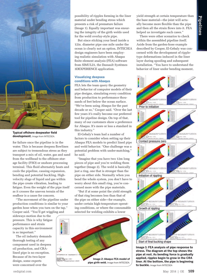
Image 1: FEA analysis of pipe response to oil production, and CRA- stress. The diagram at the top shows the lined pipe is no exception. pipe at rest. As bending force is gradually
Because of its two-layer applied, ripples begin to grow in the CRA
Image 2: Abaqus FEA model of design, some experts liner. At the bottom, the pipe is beginning
Image from INTECSEA.
pipe girth weld. were concerned over the to buckle. Image from INTECSEA oedigital.com May 2014 | OE 109 000_OE0514_pipelines1_intecsea.indd 109 4/19/14 9:53 AM