
Page 40: of Offshore Engineer Magazine (Nov/Dec 2014)
Read this page in Pdf, Flash or Html5 edition of Nov/Dec 2014 Offshore Engineer Magazine
 39
39
 41
41
in the shales using a 14.5ppg mud. well plugged back into the 9-5/8in. well objectives in the over-pressured
Subsequent drilling of 8-1/2in. hole casing.
Jurassic section of the original holes. As 2. A whipstock exit was set in 9-5/8in using 9.2ppg mud resulted in col- a part of this collaborative environment casing and 8-1/2in. hole drilled the lapse of the hole and stuck pipe. The a front-end engineering design study shales with 11.7 – 12ppg mud but was performed, which resulted in the
Drilling again the hole collapsed.
decision to drill the shale using drilling 3. The next try aimed to ? nd a suitable with liner (DwL) technology to mitigate casing depth for the 9-5/8in. to mini- the problems encountered. In this way it mize the open hole before entering the would be possible to set the liner in the depleted reservoir zone. The 9-5/8in. top of the depleted reservoir and subse- casing was cut and pull and after a quently drill it with low weight mud to whipstock in the 13-3/8in. casing prevent or at least reduce total losses. the 12-1/4in. hole was drilled using
This would require that a 11-3/4in. 14.5ppg mud. However, a suitable liner be set in the shales, safely above shoe depth couldn’t be found and total the depleted reservoir and a 9-5/8in.x losses were experienced on entering 11-3/4in. DwL section drilled through the depleted reservoir zone. The well the shale and set with the 9-5/8in. cas- was temporarily suspended pending a ing shoe into the top of the loss zone review of operational alternatives and (Fig. 2).
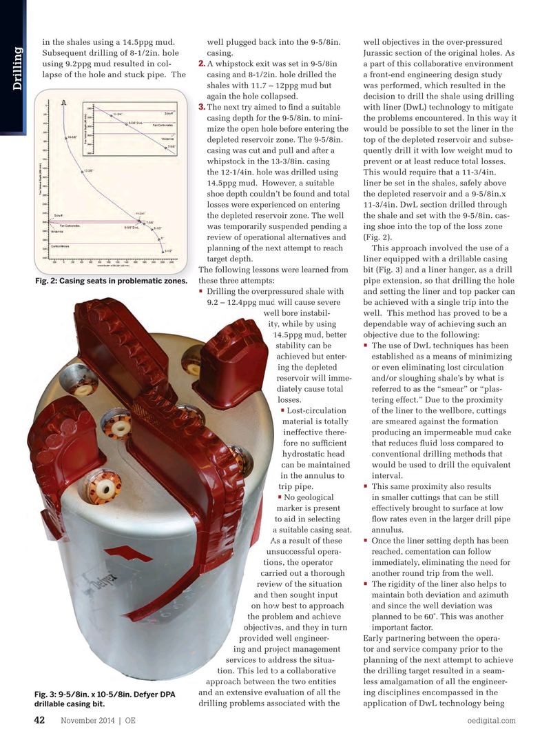
This approach involved the use of a planning of the next attempt to reach liner equipped with a drillable casing target depth.
bit (Fig.