
Page 41: of Offshore Engineer Magazine (Nov/Dec 2014)
Read this page in Pdf, Flash or Html5 edition of Nov/Dec 2014 Offshore Engineer Magazine
 40
40
 42
42
integrated into the drilling plan. This • Liner top packer 60mMD/30mTVD below bottom of
Drilling n of a detailed Polished bore receptacle • resulted in the formatio this zone in a DwL con? guration in • well engineering analysis, which took a A total length of 148m.
case of any loss of hole diameter after
The assembly was run and washed holistic approach to the well objectives. drilling it, but no such problem was down to the 11-3/4in shoe at 3273m
This analysis included torque and encountered. A successful formation and then to bottom at 3282m and drill- drag modeling to verify the mechanical integrity test to 15.5ppg was obtained ing commenced using 14.5ppg OBM integrity of the proposed liner system, proving the successful isolation of the to a depth of 3302m where ? uid losses special testing, detailed preparation of loss zone. were encountered. Drilling continued procedures and simulation modelling
However, continuous lost circula- to a depth of 3312m, at an average rate for running, drilling and cementing of tion issues appeared while drilling of 3.55m/hour at which point the liner the 9-5/8in. x 11-3/4in. liner as well as the subsequent 6-1/2in. section even got eventually stuck. Logs later con- allowing for a contingency plan to run a after successful cement squeezes. This 7-5/8in. x 9-5/8in. DwL liner in the event indicates that the upper part indicates that the upper part that the initial liner could not be drilled of the Volcanics is con-of the Volcanics is con- deep enough. nected through fractures nected through fractures
As a further contingency, in the event to the depleted reservoir to the depleted reservoir that the 7-5/8in. liner shoe is still in the formation.formation.
loss zone or inside the shale section, a In order to isolate these 200m length of 6-1/2in. expandable liner fractures, a 6in. contingency fractures, a 6in. contingency was sourced and made available. To HydraSkin solid expandable HydraSkin solid expandable prevent differential sticking in the per- liner was utilized and, due liner was utilized and, due meable depleted reservoir all liners are to the unexpected extended to the unexpected extended equipped with special designed stabiliz- length that was required, length that was required, ers even the expandable liner. an additional 260m of an additional 260m of
During the planning phase regular HydraSkin solid expand-HydraSkin solid expand- meetings were held and software to able liner had to be swiftly able liner had to be swiftly track the project scheduling was created shipped to the location. shipped to the location. to be sure that equipment deliverables Meanwhile, the 6-1/2in. would be completed in the required section was drilled and section was drilled and time frame to meet the various well subsequently enlarged to subsequently enlarged to objectives. Potential problems, drilling 7.8in. with a RipTide drilling 7.8in. with a RipTide drilling hazards and check points were estab- reamer. During the deploy-reamer. During the deploy- lished in order that both entities had a ment of the expandable ment of the expandable clear understanding of the project and liner it became differentially liner it became differentially its intricacies. This resulted in addi- stuck 230m above bottom, stuck 230m above bottom, tional equipment being sourced and most likely in the additional most likely in the additional made available, such as surge reduction section which could not be section which could not be tools, auto-? ll collars, underreamer, equipped with centralizers equipped with centralizers centralizers, etc. on short notice. The liner on short notice. The liner
The initiation of the above described was expanded and cemented was expanded and cemented collaborative endeavor commenced successfully in place, and successfully in place, and in Febuary 2013, and after a lengthy the drill out of the expand-the drill out of the expand-
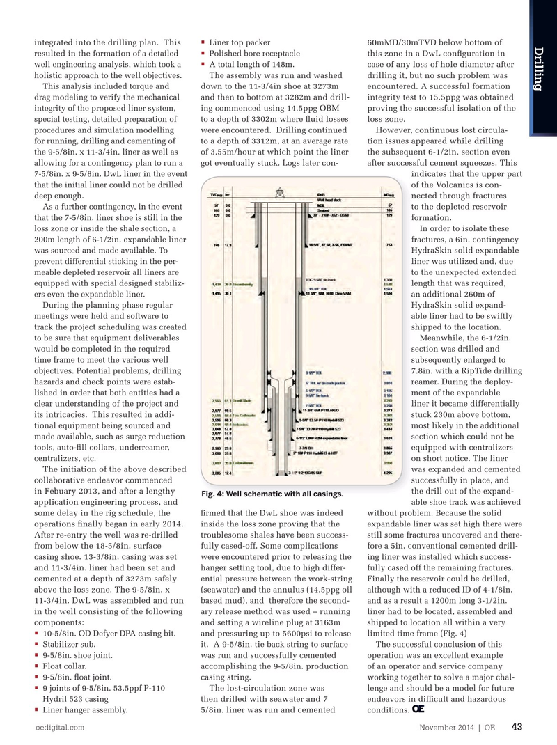
Fig. 4: Well schematic with all casings.
application engineering process, and able shoe track was achieved some delay in the rig schedule, the ? rmed that the DwL shoe was indeed without problem. Because the solid operations ? nally began in early 2014. inside the loss zone proving that the expandable liner was set high there were
After re-entry the well was re-drilled troublesome shales have been success- still some fractures uncovered and there- from below the 18-5/8in. surface fully cased-off. Some complications fore a 5in. conventional cemented drill- casing shoe. 13-3/8in. casing was set were encountered prior to releasing the ing liner was installed which success- and 11-3/4in. liner had been set and hanger setting tool, due to high differ- fully cased off the remaining fractures. cemented at a depth of 3273m safely ential pressure between the work-string
Finally the reservoir could be drilled, above the loss zone. The 9-5/8in. x (seawater) and the annulus (14.5ppg oil although with a reduced ID of 4-1/8in. 11-3/4in. DwL was assembled and run based mud), and therefore the second- and as a result a 1200m long 3-1/2in. in the well consisting of the following ary release method was used – running liner had to be located, assembled and components: and setting a wireline plug at 3163m shipped to location all within a very • 10-5/8in. OD Defyer DPA casing bit. limited time frame (Fig.