
Page 20: of Offshore Engineer Magazine (Apr/May 2015)
Read this page in Pdf, Flash or Html5 edition of Apr/May 2015 Offshore Engineer Magazine
 19
19
 21
21
which had signifcant inrush and steady state current, data is only required once the well is producing. Although it is not the control system vendor’s normal pro- cess, modifying the software to have the
WGFM “OFF” on power-up reduced the
Field of View system loading to an acceptable level for single channel operation.
Process expansion to allow the two additional manifolds to be located adja- cent to the existing structure was straight forward and achieved using tie-in spool bases, which provided the necessary separation.
Phase V added onshore “boost” compression and had no impact on the offshore development where the next expansion, WDDM phase VI, was for the addition of the Sequoia feld.
Although comprising of six wells, only three, Sequoia North, were associated with WDDM, being connected into the
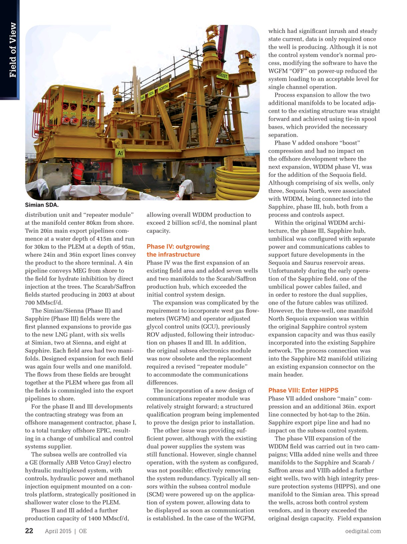
Simian SDA.
Sapphire, phase III, hub, both from a distribution unit and “repeater module” allowing overall WDDM production to process and controls aspect.
at the manifold center 80km from shore. exceed 2 billion scf/d, the nominal plant Within the original WDDM archi-
Twin 20in main export pipelines com- capacity. tecture, the phase III, Sapphire hub, mence at a water depth of 415m and run umbilical was confgured with separate
Phase IV: outgrowing for 30km to the PLEM at a depth of 95m, power and communications cables to the infrastructure where 24in and 36in export lines convey support future developments in the the product to the shore terminal. A 4in Phase IV was the frst expansion of an Sequoia and Saurus reservoir areas. pipeline conveys MEG from shore to existing feld area and added seven wells Unfortunately during the early opera- the feld for hydrate inhibition by direct and two manifolds to the Scarab/Saffron tion of the Sapphire feld, one of the injection at the trees. The Scarab/Saffron production hub, which exceeded the umbilical power cables failed, and felds started producing in 2003 at about initial control system design. in order to restore the dual supplies,
No matter where you go around the 700 MMscf/d. The expansion was complicated by the one of the future cables was utilized. world, the oil and natural gas industry
The Simian/Sienna (Phase II) and requirement to incorporate west gas fow- However, the three-well, one manifold relies on API Certifcation, API Training,
Sapphire (Phase III) felds were the meters (WGFM) and operator adjusted North Sequoia expansion was within
API Events, API Standards, API Statistics, and API Safety. Show the world your frst planned expansions to provide gas glycol control units (GCU), previously the original Sapphire control system commitment to quality. Start with API.
IT STARTS WITH API.
to the new LNG plant, with six wells ROV adjusted, following their introduc- expansion capacity and was thus easily at Simian, two at Sienna, and eight at tion on phases II and III. In addition, incorporated into the existing Sapphire
Sapphire. Each feld area had two mani- the original subsea electronics module network. The process connection was folds. Designed expansion for each feld was now obsolete and the replacement into the Sapphire M2 manifold utilizing was again four wells and one manifold. required a revised “repeater module” an existing expansion connector on the
The fows from these felds are brought to accommodate the communications main header.
together at the PLEM where gas from all differences.
Phase VIII: Enter HIPPS the felds is commingled into the export The incorporation of a new design of pipelines to shore. communications repeater module was Phase VII added onshore “main” com-
For the phase II and III developments relatively straight forward; a structured pression and an additional 36in. export the contracting strategy was from an qualifcation program being implemented line connected by hot-tap to the 26in. offshore management contractor, phase I, to prove the design prior to installation. Sapphire export pipe line and had no to a total turnkey offshore EPIC, result- The other issue was providing suf- impact on the subsea control system.
ing in a change of umbilical and control fcient power, although with the existing The phase VIII expansion of the
It’s times like these you need people like us.
systems supplier. dual power supplies the system was WDDM feld was carried out in two cam-
The subsea wells are controlled via still functional. However, single channel paigns; VIIIa added nine wells and three a GE (formally ABB Vetco Gray) electro operation, with the system as confgured, manifolds to the Sapphire and Scarab / hydraulic multiplexed system, with was not possible; effectively removing Saffron areas and VIIIb added a further controls, hydraulic power and methanol the system redundancy. Typically all sen- eight wells, two with high integrity pres-
Ofces in Washington, D.C., Houston, Beijing, Singapore, Dubai, and Rio de Janeiro. Representatives available worldwide.
injection equipment mounted on a con- sors within the subsea control module sure protection systems (HIPPS), and one 877.562.5187 (Toll-free U.S. & Canada) | +1.202.682.8041 (Local & International) | [email protected] | www.api.org trols platform, strategically positioned in (SCM) were powered up on the applica- manifold to the Simian area. This spread © 2015 – American Petroleum Institute, all rights reserved. API and the API logo are trademarks or registered trademarks of API in the United States and/or other countries.
shallower water close to the PLEM. tion of system power, allowing data to the wells, across both control system
Phases II and III added a further be displayed as soon as communication vendors, and in theory exceeded the production capacity of 1400 MMscf/d, is established. In the case of the WGFM, original design capacity. Field expansion 2015_OE_HalfPage_StartsWithAPIAd.indd 1 3/23/15 12:47 PM
April 2015 | OE oedigital.com 22 020_OE0415_Field of View.indd 22 3/23/15 2:12 PM