
Page 38: of Offshore Engineer Magazine (Aug/Sep 2015)
Read this page in Pdf, Flash or Html5 edition of Aug/Sep 2015 Offshore Engineer Magazine
 37
37
 39
39
thoroughly cleaned, dried and preserved internally.
Ensure painting, coating, surface chemi- • cal cleaning or passivation are completed
EPIC and joining areas are left in the best possible status to be completed at the site after installation.
Protect painted, coated, chemically • cleaned or passivated surfaces to avoid damage, degradation and touch-up and re-working after installation.
Sequence installation to avoid or mini- • mize mounting-dismounting as well as damage to already-installed materials and components. Heavy and large compo- nents should be installed frst.
Exotic materials that need to be segre- • gated from ferric materials are installed when the installation of carbon-steel materials is completed.
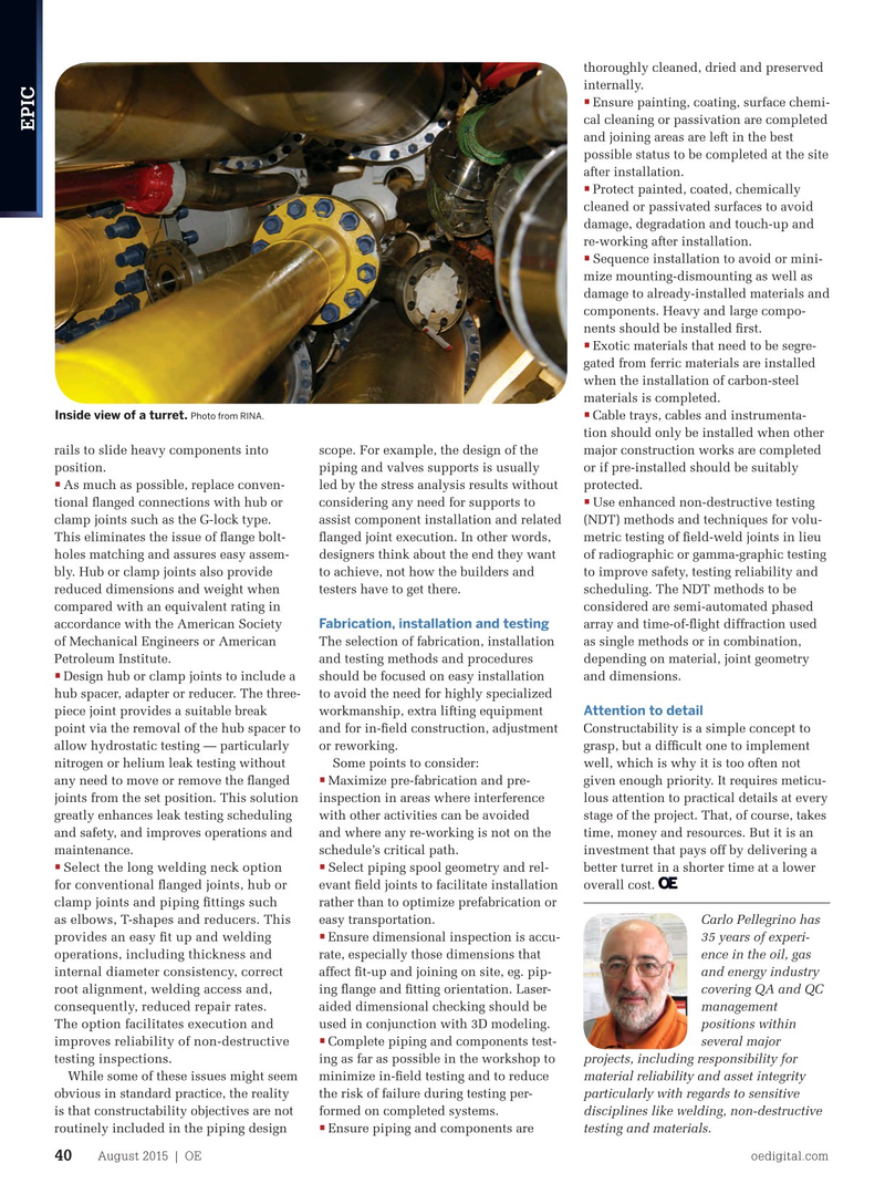
Inside view of a turret. Photo from RINA.
•
Cable trays, cables and instrumenta- tion should only be installed when other rails to slide heavy components into scope. For example, the design of the major construction works are completed position. piping and valves supports is usually or if pre-installed should be suitably •
As much as possible, replace conven- led by the stress analysis results without protected.
• tional fanged connections with hub or considering any need for supports to Use enhanced non-destructive testing clamp joints such as the G-lock type. assist component installation and related (NDT) methods and techniques for volu-
This eliminates the issue of fange bolt- fanged joint execution. In other words, metric testing of feld-weld joints in lieu holes matching and assures easy assem- designers think about the end they want of radiographic or gamma-graphic testing bly. Hub or clamp joints also provide to achieve, not how the builders and to improve safety, testing reliability and reduced dimensions and weight when testers have to get there. scheduling. The NDT methods to be compared with an equivalent rating in considered are semi-automated phased
Fabrication, installation and testing accordance with the American Society array and time-of-fight diffraction used of Mechanical Engineers or American The selection of fabrication, installation as single methods or in combination,
Petroleum Institute. and testing methods and procedures depending on material, joint geometry
Design hub or clamp joints to include a should be focused on easy installation and dimensions. • hub spacer, adapter or reducer. The three- to avoid the need for highly specialized
Attention to detail piece joint provides a suitable break workmanship, extra lifting equipment point via the removal of the hub spacer to and for in-feld construction, adjustment Constructability is a simple concept to allow hydrostatic testing — particularly or reworking. grasp, but a diffcult one to implement nitrogen or helium leak testing without Some points to consider: well, which is why it is too often not • any need to move or remove the fanged Maximize pre-fabrication and pre- given enough priority. It requires meticu- joints from the set position. This solution inspection in areas where interference lous attention to practical details at every greatly enhances leak testing scheduling with other activities can be avoided stage of the project. That, of course, takes and safety, and improves operations and and where any re-working is not on the time, money and resources. But it is an maintenance. schedule’s critical path. investment that pays off by delivering a • • Select the long welding neck option
Select piping spool geometry and rel- better turret in a shorter time at a lower for conventional fanged joints, hub or evant feld joints to facilitate installation overall cost. rather than to optimize prefabrication or clamp joints and piping fttings such as elbows, T-shapes and reducers. This easy transportation. Carlo Pellegrino has •
Ensure dimensional inspection is accu- 35 years of experi- provides an easy ft up and welding rate, especially those dimensions that ence in the oil, gas operations, including thickness and affect ft-up and joining on site, eg. pip- and energy industry internal diameter consistency, correct ing fange and ftting orientation. Laser- covering QA and QC root alignment, welding access and, aided dimensional checking should be management consequently, reduced repair rates. used in conjunction with 3D modeling. positions within
The option facilitates execution and •
Complete piping and components test- several major improves reliability of non-destructive ing as far as possible in the workshop to projects, including responsibility for testing inspections.
While some of these issues might seem minimize in-feld testing and to reduce material reliability and asset integrity obvious in standard practice, the reality the risk of failure during testing per- particularly with regards to sensitive is that constructability objectives are not formed on completed systems. disciplines like welding, non-destructive • routinely included in the piping design Ensure piping and components are testing and materials.
August 2015 | OE oedigital.com 40 038_OE0815_EPIC1_rina.indd 40 7/21/15 7:38 PM