
Page 67: of Offshore Engineer Magazine (Sep/Oct 2015)
Read this page in Pdf, Flash or Html5 edition of Sep/Oct 2015 Offshore Engineer Magazine
 66
66
 68
68
EyebrowProduction
More frequent monitoring?
permanently in a well that is being P&A’d, which could be deployed on says Neil Gardner, global sales and busi- smaller platforms, such as in Rather than permanent moni- ness development director for Ziebel. the southern North Sea, where toring requiring fbers to be a CT-like Z-System unit might installed in every well, an opera-
Z-System not ft. tor can choose to run frequent
Ziebel’s frst DFO sensing system was The result was the devel-
Z-Line runs in wells with this the Z-System, which deploys fber optic opment of the Z-Line, a intervention methodology. In cables via a 15mm diameter semi-stiff smaller 4.8mm-diameter this future vision the Z-Line carbon composite line, with carbon composite rod, using a unit very would be kept permanently on a 6600lb/3000kg breaking similar to a light coiled tubing (CT) unit. board the platform, Gardner strength, containing up to six
Once “parked” stationary in the well, the says. “Z-Line is light and can fber optic cables encased in system acquires DTS and DAS along the run in a well with a wireline a central steel tube. It comes full length of the rod. The concept for the unit. You would just have to mounted on a 1m-diameter technology was initially developed in the drop in the drum, which is drum, which can run on a early 2000s, with a patent eventually being compatible with standard wire-
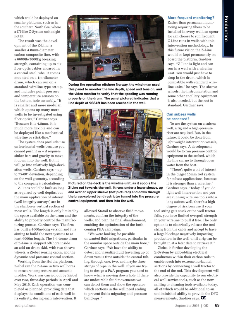
During the operation ofshore Norway, the winchman used standard wireline type set-up, granted in 2006.
line units,” he says. The sheave this panel to monitor the line depth, speed and tension, and “The idea was patented to use a carbon wheels, the instrumentation and and includes point pressure the video monitor to verify that the spooling was running composite rod with fber optics inside to some other ancillary equipment and temperature sensors on properly on the drum. The panel pictured indicates that a enter a well in order to measure param- is also needed, but the rest is the bottom hole assembly. “It line depth of 9684ft has been reached in the well.
eters like temperature, pressure and oth- standard, Gardner says.
is smaller and more modular, ers,” Gardner says.
which opens up many more
Since then, a lot of work was done Can subsea wells wells to be investigated using be accessed?
refning the product, particularly experi- fber optics,” Gardner says.
To use the system on a subsea menting with different sizes and confgura- “Because it is 4.8mm, it is well, a rig and a high-pressure tions of the rod, as well as the chemistry much more fexible and can riser are required. But, in the of the composite rod material, with the be deployed like a mechanical
University of Aberdeen providing math- future, it could be done from wireline or slick-line.”
The system does preclude use light weight intervention vessels, ematical modeling for different composite on horizontal wells because you Gardner says. A development behavior, so that it would be able to per- cannot push it in – it requires would be to run pressure control form the tasks required of it and withstand downhole conditions. sinker bars and gravity to move equipment to the seabed, which “The idea was to be able to push the it down into the well. But, it the line can go to through open semi-stiff rod out into horizontal well will go into relatively high-devi- water from the boat.
sections,” Gardner says. “The horizontal ation wells, Gardner says – up “There’s quite a bit of interest well stock is increasing and will continue to 75-80° deviation, depending in the bigger 15mm rod system to do so. The diffculty with current on the well geometry, according for subsea applications, because
Pictured on the deck is the wireline unit, as it spools the technologies is that the sensors have to to the company’s calculations. it is stronger than a wireline,”
Z-Line out towards the well. It runs under a lower sheave, up be either on the end of pipe or tractored Z-Lines could be built as long Gardner says. “Today, if you do and over an upper sheave (not pictured) and down through in on a wireline. If you can do it with as required by well depths, but light well intervention and you the brass-colored bend restrictor funnel into the pressure a carbon rod you can do away with the the main application of interest are running wireline tools into a control equipment, and then into the well.
tractor or the coiled tubing.” (well integrity surveys) are in long subsea well, there’s a high
For distributed measurements, the the shallower vertical section of degree of risk because if your allowed Statoil to observe fuid move- system has to be stationary. Unlike tradi- most wells. The length is only limited by tool string gets stuck or the well tractor ments, confrm the integrity of the tional sensors, which have to be moved the space available on the drum and the fails, you have limited overpull strength wells, and plan the fnal abandonment, across the entire zone of interest in order ability to properly control the manufac- in your wireline to pull it free. The only enabling the optimization of the forth- to get a full data set, the Z-System senses turing process, Gardner says. The frm option is to electrically release the tool coming P&A campaign.
along the whole length of the rod while has built a 4000m-long version and it is string from the cable and accept to have stationary. “We can also manipulate aiming to build the next systems to at “We were looking for possible a large blockage negatively impacting parameters in a producing well to see least 6000m length. The 3-4-tonne drum unwanted fuid migrations, particular in production in the well until a rig can be how it behaves and responds, of Z-Line is shipped offshore inside the annular space outside the main bore,” brought in at a later date to retrieve it.” such as adjusting the choke an add-on-drum skid, with two sheave Gardner says. “We have the ability to Ziebel is further developing the at surface or increasing the wheels, a Ziebel sensing cabin, and the detect and visualize fuid travelling up or Z-System by embedding electrical gas injection rate, and then dynamic seal pressure control section. down versus time outside the central tub- conductors within their carbon rods to
Working from the Huldra platform, instantly start to see the ing, through one, two, and maybe three enable reach into extreme horizontal
Ziebel ran the Z-Line in two wellbores impact of these adjustments strings of pipe in the well. If you are try- sections by connecting a well tractor to to measure temperature and acoustic across the whole well,” ing to design a P&A program you need to the end of the rod. This development will profles. Work was carried out by Ziebel
Gardner says. know what is moving down hole. If there also provide the capability to run electri- over two, three-day periods in April and are undesirable fuid movements we cal well service tools, such as the new
Z-Line
May 2015. Each operation was com- can detect them and show the operator milling or cleaning tools available today,
However, Ziebel saw the which sections in the well need sealing all of which would be additional to an pleted as planned, providing data that opportunity to develop a to prevent fuids migrating and pressure undiminished ability to provide the DFO displays the conditions of each well in smaller footprint system, build-ups.” measurements, Gardner says. its entirety, during each intervention. It oedigital.com September 2015 | OE 69 068_OE0915_ProdOps2_Ziebel.indd 69 8/20/15 10:45 AM