
Page 31: of Offshore Engineer Magazine (Mar/Apr 2024)
Read this page in Pdf, Flash or Html5 edition of Mar/Apr 2024 Offshore Engineer Magazine
 30
30
 32
32
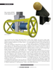
TECH FEATURE IMR to saving time and money across decades long mainte- In contrast, a new generation high sensitivity feld gra- nance regimes. dient sensor for use on ROVs and AUVs developed by
There are several methods available for measuring CP FORCE Technology employs a novel approach with its condition, and a combination of these methods may also electrodes mounted on a rotating head. Called FiGS, the be used to obtain a comprehensive understanding of the design effectively counters the issue of cell drift and the anodes' condition. The choice of method depends on fac- need for calibration. Moreover, the rotating mechanism tors like the structure's location, depth, environmental enables the sensor to determine the direction of the elec- conditions, and the specifc requirements of the mainte- tric feld. This directional insight not only provides a rela- nance plan. tive positioning for the fndings but also ensures that the
The most common form of measuring CP systems is sensor's readings are consistent, irrespective of the varying known simply as ‘stabbing’. It involves the use of a con- positions of the ROV during the survey.
tact probe (a.k.a., ‘CP stabber’) making direct contact FiGS technology integrates feld gradient detection measurement to the steel structure and the anodes, either with the measurement of protection levels (potential) by divers or ROVs. The probe typically consists of one or using non-contact sensors. The collected data is then two silver/silver chloride (Ag/AgCL) reference electrodes. merged with CP modeling to provide a comprehensive
A voltmeter measures the potential difference between the analysis. This analysis includes accurate predictions of structure and the reference electrode. the asset's lifespan, anode current output, and a poten-
The CP level of structures can be measured with con- tial profle, offering a more effcient and thorough as- ventional CP probes, provided that the structure is not sessment of maritime structures' protection against cor- buried or otherwise covered, e.g., by rock dump. As for rosion than possible with stab surveys or dual cell feld depletion of sacrifcial anodes, this can be diffcult or even gradient surveys.
impossible to estimate due to poor visibility, the presence of marine growth and/or corrosion products, or due to FiGS Operations and Benefts the anode being buried in seabed sediments or under rock Conventional approaches to evaluating cathodic pro- dump (pipelines). tection (CP) systems offer only a momentary glimpse
Proximity or cell to cell technologies which also required into their status. This limitation compels operators to frequent calibration stabs are limited to just providing a schedule CP inspections at predetermined intervals, potential profle on the structure/pipeline based on known typically every three to fve years, or to conduct CP as- formulas. Such technologies will not be accurate enough sessments opportunistically when in the vicinity. FiGS, to provide accurate calculations of anode currents to assess however, revolutionizes this process by providing detailed remaining life, nor determine issues with current drain to insights into the lifespan of the CP system. This capabil- or from adjacent structures. ity enables operators to tailor survey schedules more ef- fectively, basing them on the residual life of the anodes,
Field Gradient Technology thereby optimizing the frequency of inspections and re-
Data quality and value improves through the use of ducing maintenance costs.
non-contact surveys using feld gradient sensor technology. The system can also collect data faster than other mea-
Standard sensors in this feld work by detecting potential surement methods. A FiGS pipeline survey can be con- differences between the Ag/AgCl cells, placed approxi- ducted with an ROV fying at a speed up to 6-8 km/h mately half a meter apart, to gauge anodic and cathodic without losing valuable information. This is faster than activities. However, these cells are prone to drifting and any other advanced CP inspection tool on the market. necessitate regular recalibrations — typically after every FiGS can also be positioned higher above the pipeline and kilometer of pipeline surveyed, or every hour. still obtain valuable data. The increased speed saves costly
There are also weaknesses in terms of accuracy because vessel time, while the larger measurement distance lowers of signal noise and the ability to detect small feld gradi- the risks associated with the fight of the ROV. ents. In this process there is a risk that possible issues like Crucially, the system can be used on buried, trenched coating damages are not discovered. This can happen be- or rock dumped pipelines, obtaining the same informa- cause some of the signal peaks are interpreted as noise in- tion as for an exposed pipeline. It integrates with active stead of being picked up as coating damage. pipe trackers (e.g., TSS440) as the signals from the track-
MARCH/APRIL 2024 OFFSHORE ENGINEER 31