
Page 35: of Marine Technology Magazine (Jan/Feb 2023)
Read this page in Pdf, Flash or Html5 edition of Jan/Feb 2023 Marine Technology Magazine
 34
34
 36
36
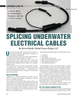
Figure 1
A potted Y-splice cable from MacArtney Underwater
Technology. The polyurethane casting (bottom right), is wide on the left side to allow for two cables and a cathode, and stepped down on the right side for a strain relief. Each cable has a locking sleeve installed before assembly. The cable on the right plugs into a single bulkhead on the command control sphere of an ocean lander. A QC tracking s/n is attached to the cable on the upper right.
Photo by Kevin Hardy nize and fuse raw rubber to a neoprene jacketed cable.
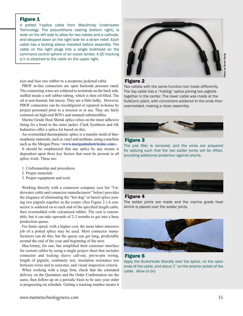
Figure 2
PBOF in-line connectors are open backside pressure rated. Two cables with the same function but made differently.
The connecting wires are soldered to terminals on the back side,
The top cable has a “hotdog” splice joining two pigtails stuffed inside a soft rubber tubing, which is then oil-? lled. The together in the center. The lower cable was made at the oil is non-hazmat, but messy. They are a little bulky. However, SubConn plant, with connectors soldered to the ends then
PBOF connectors can be recon? gured or repaired in-house by overmolded, making a clean assembly. project personnel prior to a mission or at sea. They are fairly common on high-end ROVs and manned submersibles.
Marine Grade Heat Shrink splice relies on the inner adhesive lining for a bond to the outer jacket. Clark Synthesis and AK
Industries offer a splice kit based on this.
An overmolded thermoplastic splice is a transfer mold of ther- moplastic materials, such as vinyl and urethane, using a machine
Figure 3 such as the Morgan Press
The jute ? ller is removed, and the wires are prepared
It should be emphasized that any splice by any means is for splicing such that the two solder joints will be offset, dependent upon three key factors that must be present in all providing additional protection against shorts. splice work. These are: 1. Craftsmanship and procedures 2. Proper materials 3. Proper equipment and tools
Working directly with a connector company (see list “Un- derwater cable and connector manufacturers” below) provides
Figure 4 the elegance of eliminating the “hot dog” or barrel splice join- ing two pigtails together in the center. (See Figure 2.) A con- The solder joints are made and the marine grade heat nector is soldered on to each end of the speci? ed length cable, shrink is placed over the solder joints. then overmolded with vulcanized rubber. The cost is reason- able, but it can take upwards of 2-3 months to get into a busy production queue.
For faster speed, with a higher cost, the more labor-intensive job of a potted splice may be used. Most connector manu- facturers can do this, but the queue can get long, predictably around the end of the year and beginning of the next.
MacArtney, for one, has simpli? ed their customer interface for custom cables by using a single project sheet that includes connector and locking sleeve call-out, pin-to-pin wiring,
Figure 5 length of pigtails, continuity test, insulation resistance test Apply the Scotchkote liberally over the splice, on the open between wires and to seawater, and visual inspection criteria.
ends of the cable, and about 1” on the exterior jacket of the
When working with a large ? rm, check that the estimated cable. Allow to dry delivery on the Quotation and the Order Con? rmation are the same, then follow-up on a periodic basis to be sure your order is progressing on schedule. Getting a tracking number means it www.marinetechnologynews.com 35
MTR #1 (34-47).indd 35 1/23/2023 3:15:57 PM