Page 19: of Marine Technology Magazine (March 2025)
Read this page in Pdf, Flash or Html5 edition of March 2025 Marine Technology Magazine
ature sides with the hidden ? aw,” was an adage shared by an old school Scripps’ en- gineer, Dr. Frank Snodgrass. I never forgot that wisdom. “A wreck at sea can ruin your “Nwhole day,” was a plaque centered at eye level over my desk. Another friend and shipmate, Scripps EE
Doug Peckham, had his own workbench plaque: “If it’s not tested, it won’t work.”
Failure is always an option. The secret of the most successful groups I know at Scripps, WHOI, UW, JHU, Cornell and else- where is making certain the ? rst time their system sees ten- sion, pressure, low temperature, or any other environmental condition, is before it goes over the fantail. Testing is a critical element of their success. “It should work” only plays into the hands of Davy Jones.
At Global Ocean Design, we built a simple mechanical Pull-
Test system as a means to QC critical ocean lander termina- tions, burnwires, and other tension elements under forces up to 1,200-lbs. Critical components receive 100% testing before they leave the building. The QC loop ends at our door.
The static pull test system gives con? dence in the performance of tension elements used in landers, lightweight moorings,
AUVs, and other small-to-medium scale undersea projects.
We’ve discovered links of steel chain that were not weld- ed, and pulled open under tension. Visual inspection was not helpful as the chain had been galvanized, covering the missing weld with zinc. We found the weakest link. Doesn’t happen often, but that’s de? nitely a wreck at sea that was avoided.
Likewise, we can assure swage terminations and rope splices are done to our speci? cation. We did the homework and knew what to expect. We once got rid of an expensive swage tool because it gave unreliable results.
We can con? dently determine a safety factor for tension ele- ments by taking a reasonable statistical sample to failure. It’s wise to have that margin when unpredictable sea states and ship motion may induce a snap load that could exceed 2x or more the static load.
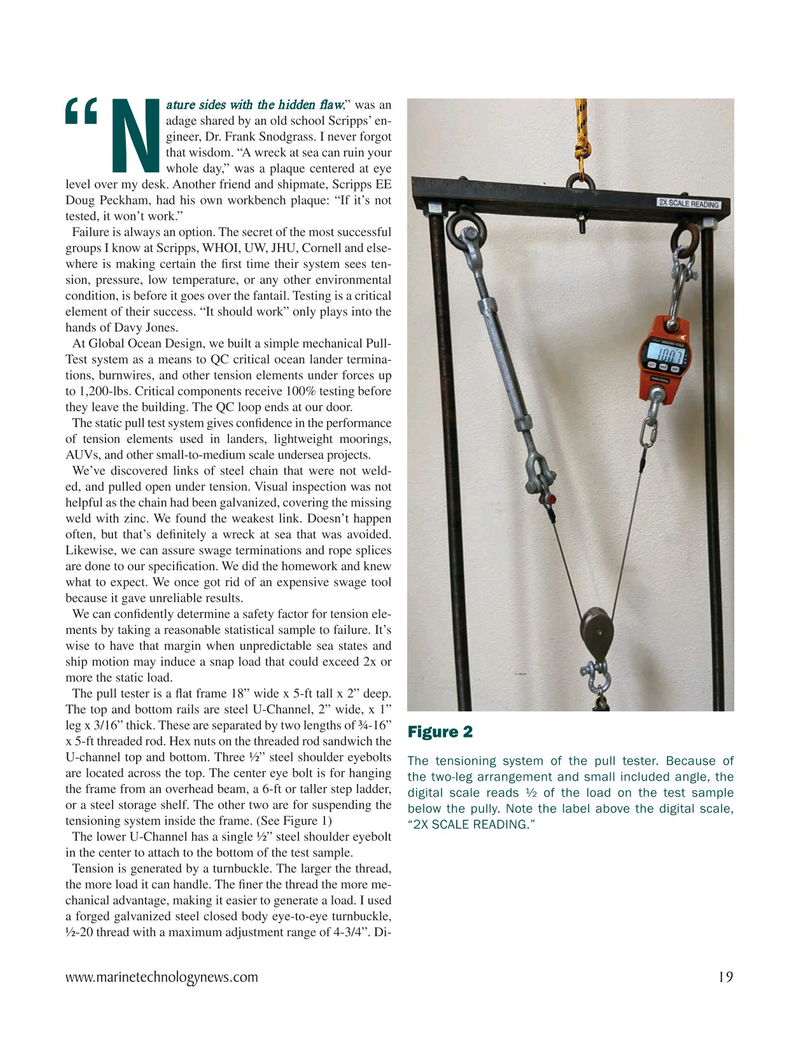
The pull tester is a ? at frame 18” wide x 5-ft tall x 2” deep.
The top and bottom rails are steel U-Channel, 2” wide, x 1” leg x 3/16” thick. These are separated by two lengths of ¾-16”
Figure 2 x 5-ft threaded rod. Hex nuts on the threaded rod sandwich the
U-channel top and bottom. Three ½” steel shoulder eyebolts The tensioning system of the pull tester. Because of are located across the top. The center eye bolt is for hanging the two-leg arrangement and small included angle, the the frame from an overhead beam, a 6-ft or taller step ladder, digital scale reads ½ of the load on the test sample or a steel storage shelf. The other two are for suspending the below the pully. Note the label above the digital scale, tensioning system inside the frame. (See Figure 1) “2X SCALE READING.”
The lower U-Channel has a single ½” steel shoulder eyebolt in the center to attach to the bottom of the test sample.
Tension is generated by a turnbuckle. The larger the thread, the more load it can handle. The ? ner the thread the more me- chanical advantage, making it easier to generate a load. I used a forged galvanized steel closed body eye-to-eye turnbuckle, ½-20 thread with a maximum adjustment range of 4-3/4”. Di- www.marinetechnologynews.com 19
MTR #3 (18-33).indd 19 3/13/2025 12:52:17 PM

 18
18

 20
20
