Page 20: of Marine Technology Magazine (March 2025)
Read this page in Pdf, Flash or Html5 edition of March 2025 Marine Technology Magazine
LANDER LAB #13 vided between the two legs, that’s 2-3/8” pull on the test sam- ing pneumatic or hydraulic rams to test sail rigging and rock- ple. The chain below the test sample allows positioning within climbing rigs that could be adapted to a computer-controlled the length of one link. The lower ½” eye bolt can be raised or system. Go to YouTube and search for “How to Build a Pull lowered to provide vernier adjustment if needed. Tester.” If anyone does this, or has done this, please write us
A 3/16” wire rope leader from the turnbuckle passes through and send a photo or two to share with your fellow Landereans.
the sheave of a 3-1/2” diameter pully, and connects to a digital We’ve made larger portable tensioning systems using a hanging scale. (See Figure 2) 12v automotive electric winch between a pair of stanchions.
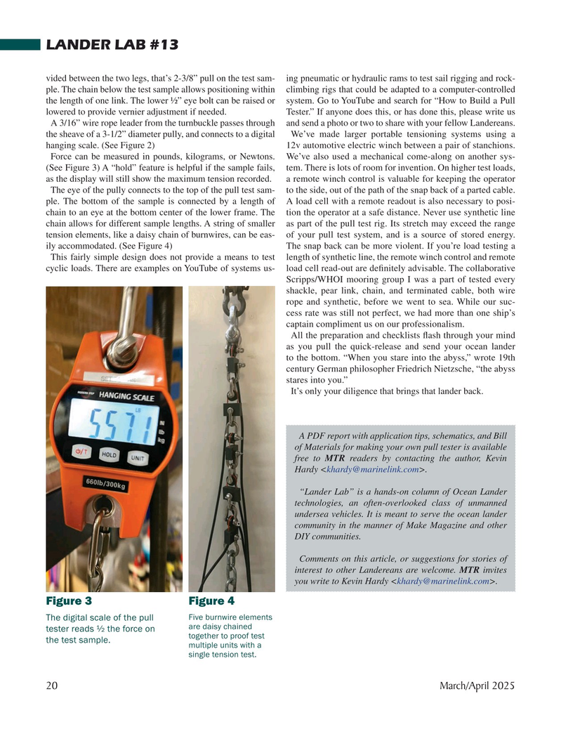
Force can be measured in pounds, kilograms, or Newtons. We’ve also used a mechanical come-along on another sys- (See Figure 3) A “hold” feature is helpful if the sample fails, tem. There is lots of room for invention. On higher test loads, as the display will still show the maximum tension recorded. a remote winch control is valuable for keeping the operator
The eye of the pully connects to the top of the pull test sam- to the side, out of the path of the snap back of a parted cable. ple. The bottom of the sample is connected by a length of A load cell with a remote readout is also necessary to posi- chain to an eye at the bottom center of the lower frame. The tion the operator at a safe distance. Never use synthetic line chain allows for different sample lengths. A string of smaller as part of the pull test rig. Its stretch may exceed the range tension elements, like a daisy chain of burnwires, can be eas- of your pull test system, and is a source of stored energy. ily accommodated. (See Figure 4) The snap back can be more violent. If you’re load testing a
This fairly simple design does not provide a means to test length of synthetic line, the remote winch control and remote cyclic loads. There are examples on YouTube of systems us- load cell read-out are de? nitely advisable. The collaborative
Scripps/WHOI mooring group I was a part of tested every shackle, pear link, chain, and terminated cable, both wire rope and synthetic, before we went to sea. While our suc- cess rate was still not perfect, we had more than one ship’s captain compliment us on our professionalism.
All the preparation and checklists ? ash through your mind as you pull the quick-release and send your ocean lander to the bottom. “When you stare into the abyss,” wrote 19th century German philosopher Friedrich Nietzsche, “the abyss stares into you.”
It’s only your diligence that brings that lander back.
A PDF report with application tips, schematics, and Bill of Materials for making your own pull tester is available free to MTR readers by contacting the author, Kevin
Hardy
“Lander Lab” is a hands-on column of Ocean Lander technologies, an often-overlooked class of unmanned undersea vehicles. It is meant to serve the ocean lander community in the manner of Make Magazine and other
DIY communities.
Comments on this article, or suggestions for stories of interest to other Landereans are welcome. MTR invites you write to Kevin Hardy
Figure 3 Figure 4
Five burnwire elements
The digital scale of the pull are daisy chained tester reads ½ the force on together to proof test the test sample.
multiple units with a single tension test.
20 March/April 2025
MTR #3 (18-33).indd 20 3/13/2025 12:52:46 PM

 19
19

 21
21
