
Page 28: of Maritime Logistics Professional Magazine (Q3 2012)
Classification Societies, Quality & Design
Read this page in Pdf, Flash or Html5 edition of Q3 2012 Maritime Logistics Professional Magazine
 27
27
 29
29
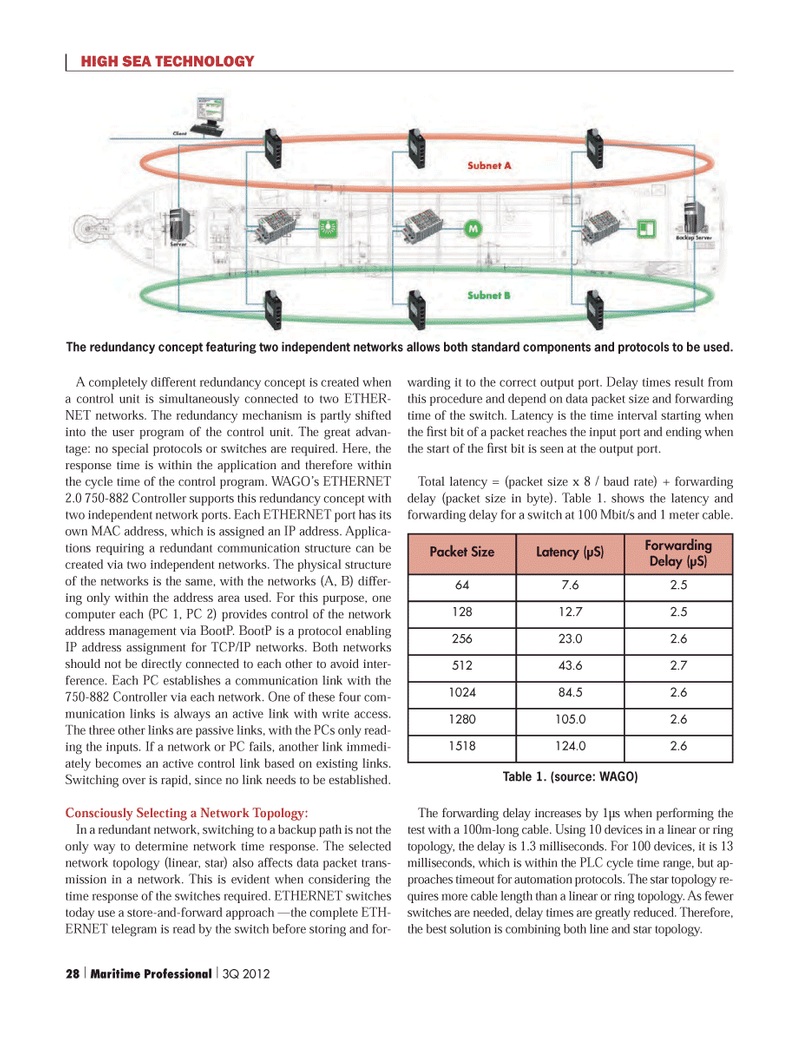
A completely different redundancy concept is created when a control unit is simultaneously connected to two ETHER- NET networks. The redundancy mechanism is partly shifted into the user program of the control unit. The great advan- tage: no special protocols or switches are required. Here, the response time is within the application and therefore within the cycle time of the control program. WAGO?s ETHERNET 2.0 750-882 Controller supports this redundancy concept with two independent network ports. Each ETHERNET port has its own MAC address, which is assigned an IP address. Applica- tions requiring a redundant communication structure can be created via two independent networks. The physical structure of the networks is the same, with the networks (A, B) differ- ing only within the address area used. For this purpose, one computer each (PC 1, PC 2) provides control of the network address management via BootP. BootP is a protocol enabling IP address assignment for TCP/IP networks. Both networks should not be directly connected to each other to avoid inter- ference. Each PC establishes a communication link with the 750-882 Controller via each network. One of these four com- munication links is always an active link with write access. The three other links are passive links, with the PCs only read- ing the inputs. If a network or PC fails, another link immedi- ately becomes an active control link based on existing links. Switching over is rapid, since no link needs to be established. Consciously Selecting a Network Topology: In a redundant network, switching to a backup path is not the only way to determine network time response. The selected network topology (linear, star) also affects data packet trans- mission in a network. This is evident when considering the time response of the switches required. ETHERNET switches today use a store-and-forward approach ?the complete ETH- ERNET telegram is read by the switch before storing and for- warding it to the correct output port. Delay times result from this procedure and depend on data packet size and forwarding time of the switch. Latency is the time interval starting when the rst bit of a packet reaches the input port and ending when the start of the rst bit is seen at the output port. Total latency = (packet size x 8 / baud rate) + forwarding delay (packet size in byte). Table 1. shows the latency and forwarding delay for a switch at 100 Mbit/s and 1 meter cable. The forwarding delay increases by 1µs when performing the test with a 100m-long cable. Using 10 devices in a linear or ring topology, the delay is 1.3 milliseconds. For 100 devices, it is 13 milliseconds, which is within the PLC cycle time range, but ap- proaches timeout for automation protocols. The star topology re- quires more cable length than a linear or ring topology. As fewer switches are needed, delay times are greatly reduced. Therefore, the best solution is combining both line and star topology. HIGH SEA TECHNOLOGY Packet SizeLatency (µS) Forwarding Delay (µS) 647.62.512812.72.525623.02.651243.62.7102484.52.61280105.02.61518124.02.6The redundancy concept featuring two independent networks allows both standard components and protocols to be used. Table 1. (source: WAGO) 28 | Maritime Professional | 3Q 2012