
Page 18: of Maritime Logistics Professional Magazine (Q1 2013)
Maritime Risk
Read this page in Pdf, Flash or Html5 edition of Q1 2013 Maritime Logistics Professional Magazine
 17
17
 19
19
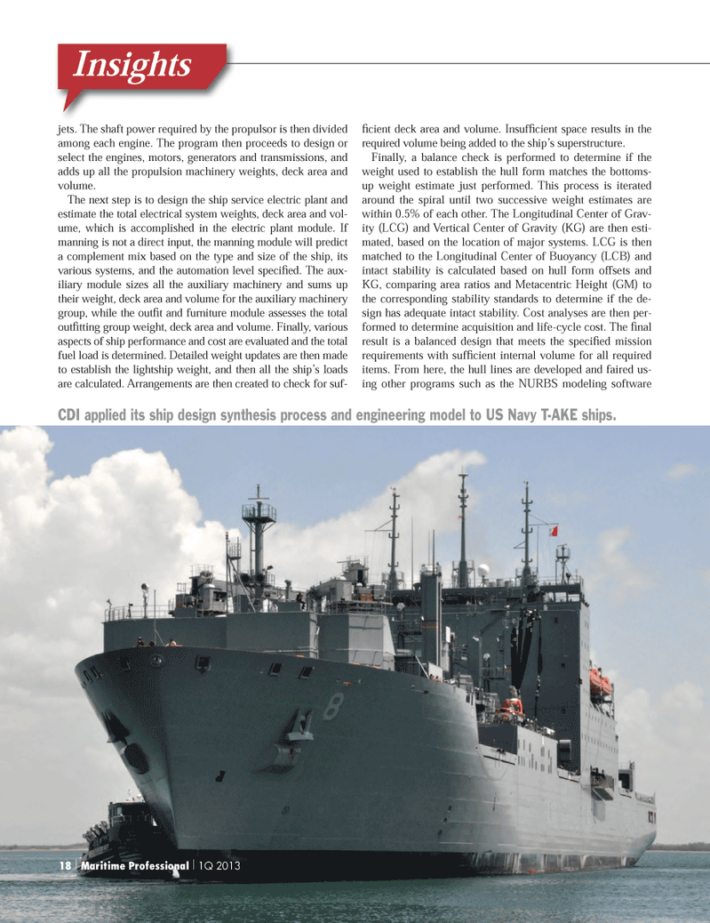
Insightsjets. The shaft power required by the propulsor is then divided among each engine. The program then proceeds to design or select the engines, motors, generators and transmissions, and adds up all the propulsion machinery weights, deck area and volume. The next step is to design the ship service electric plant and estimate the total electrical system weights, deck area and vol- ume, which is accomplished in the electric plant module. If manning is not a direct input, the manning module will predict a complement mix based on the type and size of the ship, its various systems, and the automation level speciÞ ed. The aux- iliary module sizes all the auxiliary machinery and sums up their weight, deck area and volume for the auxiliary machinery group, while the outÞ t and furniture module assesses the total outÞ tting group weight, deck area and volume. Finally, various aspects of ship performance and cost are evaluated and the total fuel load is determined. Detailed weight updates are then made to establish the lightship weight, and then all the shipÕs loads are calculated. Arrangements are then created to check for suf- Þ cient deck area and volume. InsufÞ cient space results in the required volume being added to the shipÕs superstructure. Finally, a balance check is performed to determine if the weight used to establish the hull form matches the bottoms-up weight estimate just performed. This process is iterated around the spiral until two successive weight estimates are within 0.5% of each other. The Longitudinal Center of Grav- ity (LCG) and Vertical Center of Gravity (KG) are then esti- mated, based on the location of major systems. LCG is then matched to the Longitudinal Center of Buoyancy (LCB) and intact stability is calculated based on hull form offsets and KG, comparing area ratios and Metacentric Height (GM) to the corresponding stability standards to determine if the de-sign has adequate intact stability. Cost analyses are then per- formed to determine acquisition and life-cycle cost. The Þ nal result is a balanced design that meets the speciÞ ed mission requirements with sufÞ cient internal volume for all required items. From here, the hull lines are developed and faired us- ing other programs such as the NURBS modeling software CDI applied its ship design synthesis process and engineering model to US Navy T-AKE ships. 18 | Maritime Professional | 1Q 2013MP #1 18-33.indd 18MP #1 18-33.indd 182/22/2013 11:05:41 AM2/22/2013 11:05:41 AM