Page 16: of Maritime Reporter Magazine (February 15, 1969)
Read this page in Pdf, Flash or Html5 edition of February 15, 1969 Maritime Reporter Magazine
 15
15
 17
17
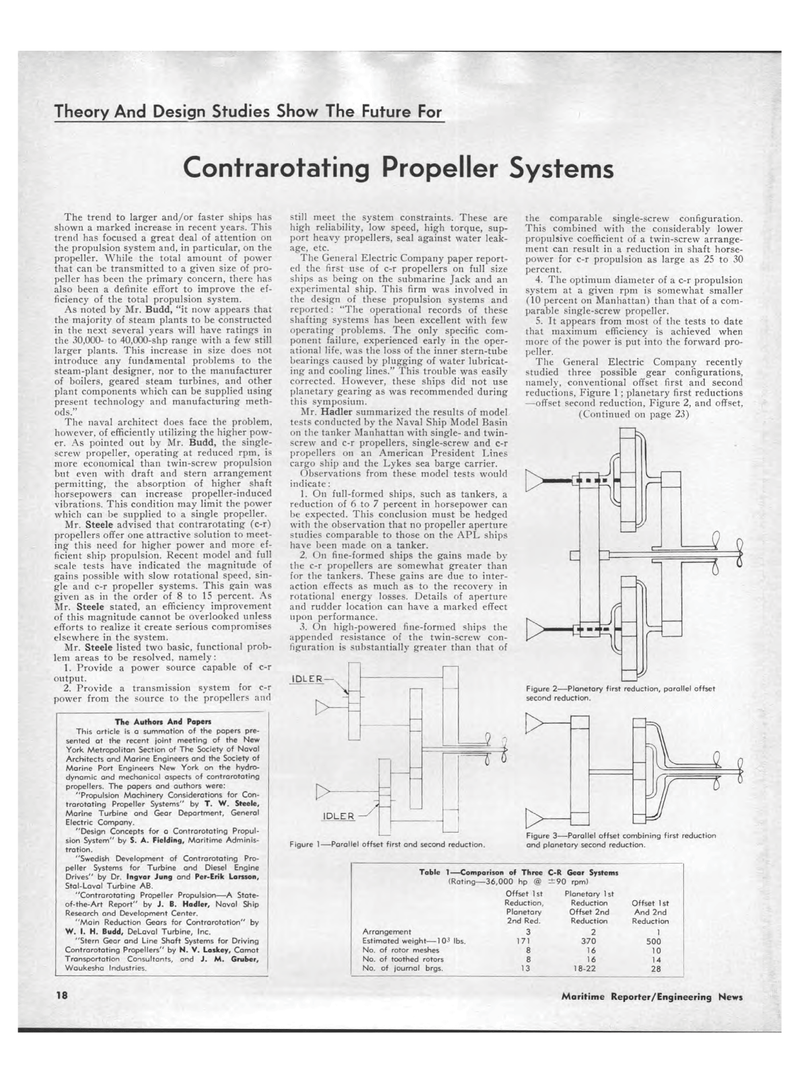
Theory And Design Studies Show The Future For Contrarotating Propeller Systems The trend to larger and/or faster ships has shown a marked increase in recent years. This trend has focused a great deal of attention on the propulsion system and, in particular, on the propeller. While the total amount of power that can be transmitted to a given size of pro-peller has been the primary concern, there has also been a definite effort to improve the ef-ficiency of the total propulsion system. As noted by Mr. Budd, "it now appears that the majority of steam plants to be constructed in the next several years will have ratings in the 30,000- to 40,000-shp range with a few still larger plants. This increase in size does not introduce any fundamental problems to the steam-plant designer, nor to the manufacturer of boilers, geared steam turbines, and other plant components which can be supplied using present technology and manufacturing meth-ods." The naval architect does face the problem, however, of efficiently utilizing the higher pow-er. As pointed out by Mr. Budd, the single-screw propeller, operating at reduced rpm, is more economical than twin-screw propulsion but even with draft and stern arrangement permitting, the absorption of higher shaft horsepowers can increase propeller-induced vibrations. This condition may limit the power which can be supplied to a single propeller. Mr. Steele advised that contrarotating (c-r) propellers offer one attractive solution to meet-ing this need for higher power and more ef-ficient ship propulsion. Recent model and full scale tests have indicated the magnitude of gains possible with slow rotational speed, sin-gle and c-r propeller systems. This gain was given as in the order of 8 to 15 percent. As Mr. Steele stated, an efficiency improvement of this magnitude cannot be overlooked unless efforts to realize it create serious compromises elsewhere in the system. Mr. Steele listed two basic, functional prob-lem areas to be resolved, namely: 1. Provide a power source capable of c-r output. 2. Provide a transmission system for c-r power from the source to the propellers and The Authors And Papers This article is a summation of the papers pre-sented ot the recent joint meeting of the New York Metropolitan Section of The Society of Naval Architects and Marine Engineers and the Society of Marine Port Engineers New York on the hydro-dynamic and mechanical aspects of contrarotating propellers. The papers and authors were: "Propulsion Machinery Considerations for Con-trarotating Propeller Systems" by T. W. Steele, Marine Turbine and Gear Department, General Electric Company. "Design Concepts for a Contrarotating Propul-sion System" by S. A. Fielding, Maritime Adminis-tration. "Swedish Development of Contrarotating Pro-peller Systems for Turbine and Diesel Engine Drives" by Dr. Ingvar Jung and Per-Erik Larsson, Stal-Laval Turbine AB. "Contrarotating Propeller Propulsion?A State-of-the-Art Report" by J. B. Hadler, Naval Ship Research and Development Center. "Main Reduction Gears for Contrarotation" by W. I. H. Budd, DeLaval Turbine, Inc. "Stern Gear and Line Shaft Systems for Driving Contrarotating Propellers" by N. V. Laskey, Camat Transportation Consultants, and J. M. Gruber, Waukesha Industries. Still meet the system constraints. These are high reliability, low speed, high torque, sup-port heavy propellers, seal against water leak-age, etc. The General Electric Company paper report-ed the first use of c-r propellers on full size ships as being on the submarine Jack and an experimental ship. This firm was involved in the design of these propulsion systems and reported: "The operational records of these shafting systems has been excellent with few operating problems. The only specific com-ponent failure, experienced early in the oper-ational life, was the loss of the inner stern-tube bearings caused by plugging of water lubricat-ing and cooling lines." This trouble was easily corrected. However, these ships did not use planetary gearing as was recommended during this symposium. Mr. Hadler summarized the results of model tests conducted by the Naval Ship Model Basin on the tanker Manhattan with single- and twin-screw and c-r propellers, single-screw and c-r propellers on an American President Lines cargo ship and the Lykes sea barge carrier. Observations from these model tests would indicate : 1. On full-formed ships, such as tankers, a reduction of 6 to 7 percent in horsepower can be expected. This conclusion must be hedged with the observation that no propeller aperture studies comparable to those on the APL ships have been made on a tanker. 2. On fine-formed ships the gains made by the c-r propellers are somewhat greater than for the tankers. These gains are due to inter-action effects as much as to the recovery in rotational energy losses. Details of aperture and rudder location can have a marked effect upon performance. 3. On high-powered fine-formed ships the appended resistance of the twin-screw con-figuration is substantially greater than that of IDLER?x D> t> IDLER 1 Figure l?Parallel offset first and second reduction. the comparable single-screw configuration. This combined with the considerably lower propulsive coefficient of a twin-screw arrange-ment can result in a reduction in shaft horse-power for c-r propulsion as large as 25 to 30 percent. 4. The optimum diameter of a c-r propulsion system at a given rpm is somewhat smaller (10 percent on Manhattan) than that of a com-parable single-screw propeller. 5. It appears from most of the tests to date that maximum efficiency is achieved when more of the power is put into the forward pro-peller. The General Electric Company recently studied three possible gear configurations, namely, conventional offset first and second reductions, Figure 1; planetary first reductions ?offset second reduction, Figure 2, and offset, (Continued on page 23) It 2 Figure 2?Planetary first reduction, parallel offset second reduction. Figure 3?Parallel offset combining first reduction and planetary second reduction. Table 1?Comparison of Three C-R Gear Systems (Rating-?36,000 hp @ ±90 rpm) Offset 1st Planetary 1st Reduction, Reduction Offset 1st Planetary Offset 2nd And 2nd 2nd Red. Reduction Reduction Arrangement 3 2 1 Estimated weight?1 03 lbs. 171 370 500 No. of rotor meshes 8 16 10 No. of toothed rotors 8 16 14 No. of journal brgs. 13 18-22 28 18 Maritime Reporter/Engineering News
