Page 17: of Maritime Reporter Magazine (February 15, 1969)
Read this page in Pdf, Flash or Html5 edition of February 15, 1969 Maritime Reporter Magazine
 16
16
 18
18
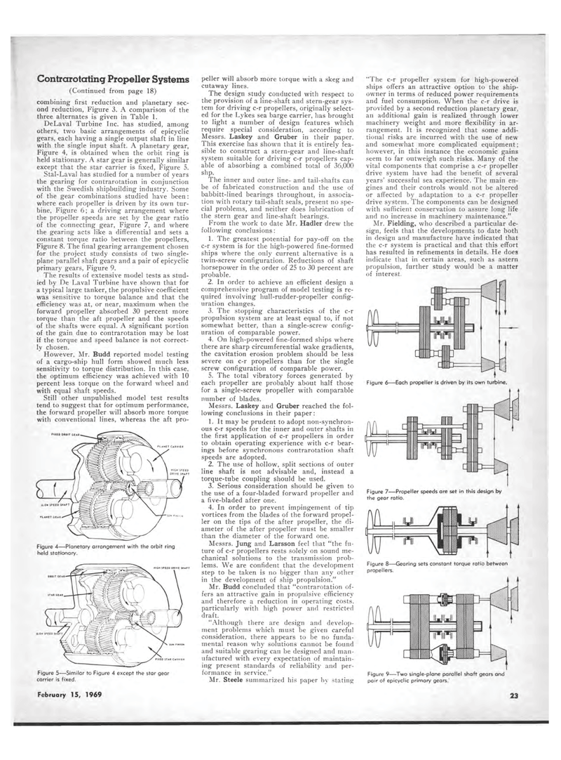
Contrarotating Propeller Systems (Continued from page 18) combining first reduction and planetary sec-ond reduction, Figure 3. A comparison of the three alternates is given in Table 1. DeLaval Turbine Inc. has studied, among others, two basic arrangements of epicyclic gears, each having a single output shaft in line with the single input shaft. A planetary gear, Figure 4, is obtained when the orbit ring is held stationary. A star gear is generally similar except that the star carrier is fixed, Figure 5. Stal-Laval has studied for a number of years the gearing for contrarotation in conjunction with the Swedish shipbuilding industry. Some of the gear combinations studied have been: where each propeller is driven by its own tur-bine, Figure 6; a driving arrangement where the propeller speeds are set by the gear ratio of the connecting gear, Figure 7, and where the gearing acts like a differential and sets a constant torque ratio between the propellers, Figure 8. The final gearing arrangement chosen for the project study consists of two single-plane parallel shaft gears and a pair of epicyclic primary gears, Figure 9. The results of extensive model tests as stud-ied by De Laval Turbine have shown that for a typical large tanker, the propulsive coefficient was sensitive to torque balance and that the efficiency was at, or near, maximum when the forward propeller absorbed 30 percent more torque than the aft propeller and the speeds of the shafts were equal. A significant portion of the gain due to contrarotation may be lost if the torque and speed balance is not correct-ly chosen. However, Mr. Budd reported model testing of a cargo-ship hull form showed much less sensitivity to torque distribution. In this case, the optimum efficiency was achieved with 10 percent less torque on the forward wheel and with equal shaft speeds. Still other unpublished model test results tend to suggest that for optimum performance, the forward propeller will absorb more torque with conventional lines, whereas the aft pro-PIXED ORBIT GEAR PL AHET CARRIER HICH SPEED DRIVE SHAFT PLANET GEAR Figure 4?Planetary arrangement with the orbit ring held stationary. HIGH SPEED DRIVE SHAFT ORBIT GEAR Figure 5?Similar to Figure 4 except the star gear carrier is fixed. peller will absorb more torque with a skeg and cutaway lines. The design study conducted with respect to the provision of a line-shaft and stern-gear sys-tem for driving c-r propellers, originally select-ed for the Lykes sea barge carrier, has brought to light a number of design features which require special consideration, according to Messrs. Laskey and Gruber in their paper. This exercise has shown that it is entirely fea-sible to construct a stern-gear and line-shaft system suitable for driving c-r propellers cap-able of absorbing a combined total of 36,000 shp. The inner and outer line- and tail-shafts can be of fabricated construction and the use of babbitt-lined bearings throughout, in associa-tion with rotary tail-shaft seals, present no spe-cial problems, and neither does lubrication of the stern gear and line-shaft bearings. From the work to date Mr. Hadler drew the following conclusions: 1. The greatest potential for pay-off on the c-r system is for the high-powered fine-formed ships where the only current alternative is a twin-screw configuration. Reductions of shaft horsepower in the order of 25 to 30 percent are probable. 2. In order to achieve an efficient design a comprehensive program of model testing is re-quired involving hull-rudder-propeller config-uration changes. 3. The stopping characteristics of the c-r propulsion system are at least equal to, if not somewhat better, than a single-screw config-uration of comparable power. 4. On high-powered fine-formed ships where there are sharp circumferential wake gradients, the cavitation erosion problem should be less severe on c-r propellers than for the single screw configuration of comparable power. 5. The total vibratory forces generated by each propeller are probably about half those for a single-screw propeller with comparable number of blades. Messrs. Laskey and Gruber reached the fol-lowing conclusions in their paper: 1. It may be prudent to adopt non-synchron-ous c-r speeds for the inner and outer shafts in the first application of c-r propellers in order to obtain operating experience with c-r bear-ings before synchronous contrarotation shaft speeds are adopted. 2. The use of hollow, split sections of outer line shaft is not advisable and, instead a torque-tube coupling should be used. 3. Serious consideration should be given to the use of a four-bladed forward propeller and a five-bladed after one. 4. In order to prevent impingement of tip vortices from the blades of the forward propel-ler on the tips of the after propeller, the di-ameter of the after propeller must be smaller than the diameter of the forward one. Messrs. Jung and Larsson feel that "the fu-ture of c-r propellers rests solely on sound me-chanical solutions to the transmission prob-lems. We are confident that the development step to be taken is no bigger than any other in the development of ship propulsion." Mr. Budd concluded that "contrarotation of-fers an attractive gain in propulsive efficiency and therefore a reduction in operating costs, particularly with high power and restricted draft. "Although there are design and develop-ment problems which must be given careful consideration, there appears to be no funda-mental reason why solutions cannot be found and suitable gearing can be designed and man-ufactured with every expectation of maintain-ing present standards of reliability and per-formance in service." Mr. Steele summarized his paper bv stating "The c-r propeller system for high-powered ships offers an attractive option to the ship-owner in terms of reduced power requirements and fuel consumption. When the c-r drive is provided by a second reduction planetary gear, an additional gain is realized through lower machinery weight and more flexibility in ar-rangement. It is recognized that some addi-tional risks are incurred with the use of new and somewhat more complicated equipment; however, in this instance the economic gains seem to far outweigh such risks. Many of the vital components that comprise a c-r propeller drive system have had the benefit of several years' successful sea experience. The main en-gines and their controls would not be altered or affected by adaptation to a c-r propeller drive system. The components can be designed with sufficient conservation to assure long life and no increase in machinery maintenance." Mr. Fielding, who described a particular de-sign, feels that the developments to date both in design and manufacture have indicated that the c-r system is practical and that this effort has resulted in refinements in details. He does indicate that in certain areas, such as astern propulsion, further study would be a matter of interest. Figure 6?Each propeller is driven by its own turbine. Figure 7?Propeller speeds are set in this design by the gear ratio. Figure 8?-Gearing sets constant torque ratio between propellers. Figure 9?Two single-plane parallel shaft gears and pair of epicyclic primary gears.' February 23, 1969 11
