Page 12: of Maritime Reporter Magazine (May 15, 1969)
Read this page in Pdf, Flash or Html5 edition of May 15, 1969 Maritime Reporter Magazine
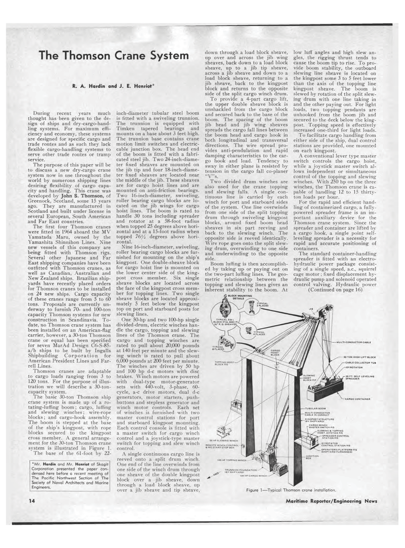
The Thomson Crane System R. A. Hardin and J. E. Henriot* During recent years much thought has been given to the de-sign of ships and dry-cargo-hand-ling systems. For maximum effi-ciency and economy, these systems are designed for specific cargo and trade routes and as such they lack flexible cargo-handling systems to serve other trade routes or tramp service. The purpose of this paper will be to discuss a new dry-cargo crane system now in use throughout the world by numerous shipping lines desiring flexibility of cargo capa-city and handling. This crane was developed by John S. Thomson, of Greenock, Scotland, some 15 years ago. They are manufactured in Scotland and built under license in several European, South American and Far East countries. The first four Thomson cranes were fitted in 1964 aboard the MV Yamatada Maru, owned by the Yamashita Shinnihon Lines. Nine new vessels of this company are being fitted with Thomson rigs. Several other Japanese and Far East shipping companies have been outfitted with Thomson cranes, as well as Canadian, Australian and New Zealand ships. Brazilian ship-yards have recently placed orders for Thomson cranes to be installed on 24 new ships. Cargo capacity of these cranes range from 5 to 60 tons. Proposals are currently un-derway to furnish 70- and 100-ton capacity Thomson systems for new construction in Scandinavia. To-date, no Thomson crane system has been installed on an American-flag carrier, however, a 30-ton Thomson crane or equal has been specified for seven MarAd Design C6-S-85-a/b ships to be built by Ingalls Shipbuilding Corporation for American President Lines and Far-rell Lines. Thomson cranes are adaptable to cargo loads ranging from 3 to 120 tons. For the purpose of illus-tration we will describe a 30-ton-capacity system. The basic 30-ton Thomson ship crane system is made up of a ro-tating-luffing boom ; cargo, luffing and slewing winches; wire-rope blocks; and cargo-hook assembly. The boom is stepped at the base of the ship's kingpost, with rope blocks secured to the kingpost cross member. A general arrange-ment for the 30-ton Thomson crane system is illustrated in Figure 1. The base of the 61-foot by 22-*Mr. Hardin and Mr. Henriot of Skagit Corporation presented the paper con-densed here before a recent meeting of The Pacific Northwest Section of The Society of Naval Architects and Marine Engineers. 14 inch-diameter tubular steel boom is fitted with a swiveling trunnion. The trunnion is equipped with Timken tapered bearings and mounts on a base about 3 feet high. The trunnion base contains crane motion limit switches and electric-cable junction box. The head end of the boom is fitted with a fabri-cated steel jib. Two 24-inch-diame-ter fixed sheaves are mounted on the jib tip and four 18-inch-diame-ter fixed sheaves are located near the middle of the jib. These sheaves are for cargo hoist lines and are mounted on anti-friction bearings. Two 16-inch-diameter, swiveling, roller bearing cargo blocks are lo-cated on the jib wings for cargo hoist lines. The boom is rated to handle 30 tons including spreader and rotator at a 58-foot radius when topped 25 degrees above hori-zontal and at a 15-foot radius when topped 76l/2 degrees above hori-zontal. Nine 16-inch-diameter, swiveling, roller bearing cargo blocks are fur-nished for mounting on the ship's kingpost. One double-sheave block for cargo hoist line is mounted on the lower center side of the king-post cross member. Six single sheave blocks are located across the face of the kingpost cross mem-ber for topping lines. Two single sheave blocks are located approxi-mately 5 feet below the kingpost top on port and starboard posts for slewing lines. One 50-hp and two 100-hp single divided-drum, electric winches han-dle the cargo, topping and slewing lines of the Thomson crane. The cargo and topping winches are rated to pull about 20,000 pounds at 140 feet per minute and the slew-ing winch is rated to pull about 6,000 pounds at 200 feet per minute. The winches are driven by 50 hp and 100 hp d-c motors with disc brakes. Winch motors are powered with dual-type motor-generator sets with 440-volt, 3-phase, 60-cycle, a-c drive motors, dual d-c generators, motor starters, push-buttons and stepless generator and winch motor controls. Each set of winches is furnished with two master control stations for port and starboard kingpost mounting. Each control console is fitted with a master switch for cargo winch control and a joystick-type master switch for topping and slew winch control. A single continuous cargo line is reeved onto a split drum winch. One end of the line overwinds from one side of the winch drum through one sheave of the double kingpost block over a jib sheave, down through a load block sheave, up over a jib sheave and tip sheave, clown through a load block sheave, up over and across the jib wing sheaves, back down to a load block sheave, up to a jib tip sheave, across a jib sheave and down to a load block sheave, returning to a jib sheave, back to the kingpost block and returns to the opposite side of the split cargo winch drum. To provide a 4-part cargo lift, the upper double sheave block is unshackled from the cargo block and secured back to the base of the boom. The spacing of the boom jib head and jib wing sheaves spreads the cargo fall lines between the boom head and cargo hook in both longitudinal and transversal directions. The wire spread pro-vides anti-pendulation and rapid damping characteristics to the car-go hook and load. Tendency to sway in either plane is resisted by tension in the cargo fall co-planer "V"s. Two divided drum winches are also used for the crane topping and slewing falls. A single con-tinuous line is carried by each winch for port and starboard sides of the system. One line overwinds from one side of the split topping drum through swiveling kingpost blocks, around fixed boom head sheaves in six part reeving and back to the slewing winch. The opposite side is reeved identically. Wire rope goes onto the split slew-ing drum, overwinding to one side and underwinding to the opposite side. Boom luffing is then accomplish-ed by taking up or paying out on the two-part luffing lines. The geo-metric relationship between the topping and slewing lines gives an inherent stability to the boom. At low luff angles and high slew an-gles, the rigging thrust tends to cause the boom tip to rise. To pro-vide boom stability, the outboard slewing line sheave is located on the kingpost some 3 to 5 feet lower than the axis of the topping line kingpost sheave. The boom is slewed by rotation of the split slew-ing drum with one line taking in and the other paying out. For light loads, two topping pendants are unhooked from the boom jib and secured to the deck below the king-post. Topping speed is effectively increased one-third for light loads. To facilitate cargo handling from either side of the ship, dual control stations are provided, one mounted on each kingpost. A conventional lever type master switch controls the cargo hoist, while a joystick master switch al-lows independent or simultaneous control of the topping and slewing winches. With 250 hp on the three winches, the Thomson crane is ca-pable of handling 12 to 15 thirty-ton loads per hour. For the rapid and efficient hand-ling of containerized cargo, a fully-powered spreader frame is an im-portant auxiliary device for the Thomson crane system. Since the spreader and container are lifted by a cargo hook, a single point self-leveling spreader is a necessity for rapid and accurate positioning of containers. The standard container-handling spreader is fitted with an electro-hydraulic power package consist-ing of a single speed, a.c., squirrel cage motor; fixed displacement hy-draulic pump and solenoid operated control valving. Hydraulic power (Continued on page 16) JIB MULTI-CONDUCTOR CASLE 30 TON HIGH LIFT BLOCK CABLE COLLECTOR TUB GYROTATOR CARGO CONTAINER SLEWING it TOPPING HOIST JOYSTICK P/S SPREADER CONTROL STATION P/S lOO HP TOPPING WINCH 1OO HP CARGO WINCH Figure 1?Typical Thomson crane installation. Maritime Reporter/Engineering News

 11
11

 13
13
