Page 30: of Maritime Reporter Magazine (July 15, 1969)
Read this page in Pdf, Flash or Html5 edition of July 15, 1969 Maritime Reporter Magazine
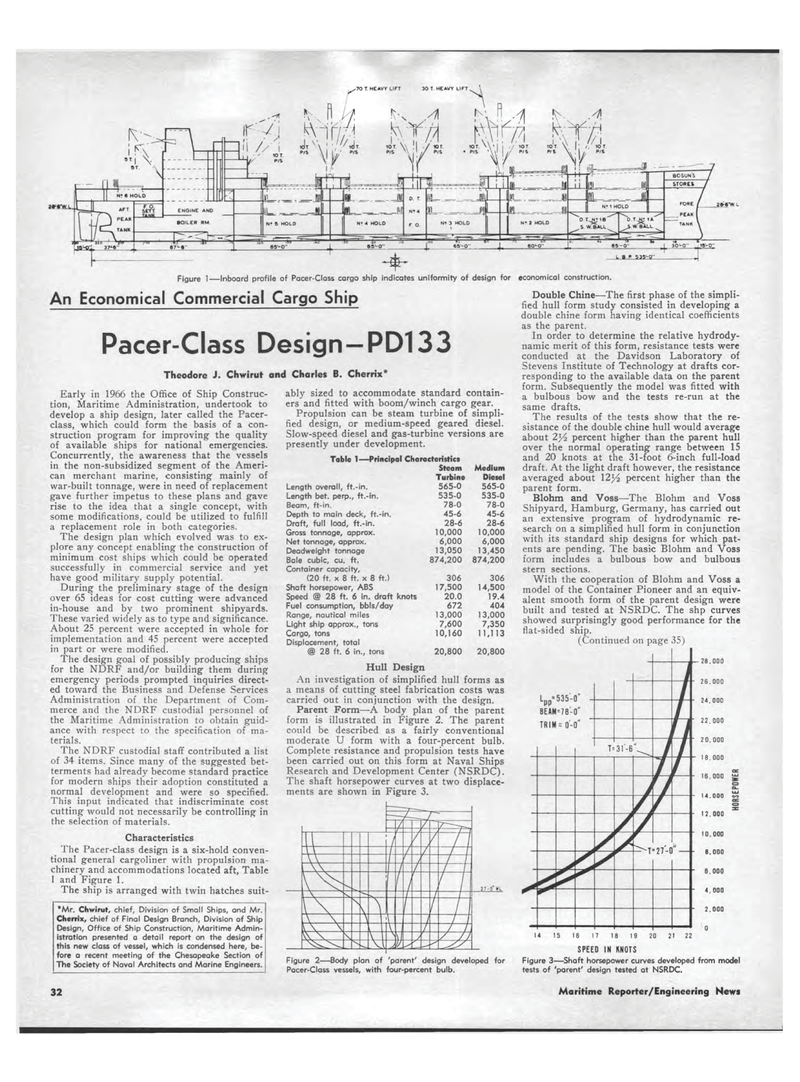
r 70 T. HEAVY LIFT 30 T HEAVY LIFT JHWl-Figure 1?Inboard profile of Pacer-Class cargo ship indicates uniformity of design for economical construction. An Economical Commercial Cargo Ship Pacer-Class Design-PD133 Theodore J. Chwirut and Charles B. Cherrix* Early in 1966 the Office of Ship Construc-tion, Maritime Administration, undertook to develop a ship design, later called the Pacer-class, which could form the basis of a con-struction program for improving the quality of available ships for national emergencies. Concurrently, the awareness that the vessels in the non-subsidized segment of the Ameri-can merchant marine, consisting mainly of war-built tonnage, were in need of replacement gave further impetus to these plans and gave rise to the idea that a single concept, with some modifications, could be utilized to fulfill a replacement role in both categories. The design plan which evolved was to ex-plore any concept enabling the construction of minimum cost ships which could be operated successfully in commercial service and yet have good military supply potential. During the preliminary stage of the design over 65 ideas for cost cutting were advanced in-house and by two prominent shipyards. These varied widely as to type and significance. About 25 percent were accepted in whole for implementation and 45 percent were accepted in part or were modified. The design goal of possibly producing ships for the NDRF and/or building them during emergency periods prompted inquiries direct-ed toward the Business and Defense Services Administration of the Department of Com-merce and the NDRF custodial personnel of the Maritime Administration to obtain guid-ance with respect to the specification of ma-terials. The NDRF custodial staff contributed a list of 34 items. Since many of the suggested bet-terments had already become standard practice for modern ships their adoption constituted a normal development and were so specified. This input indicated that indiscriminate cost cutting would not necessarily be controlling in the selection of materials. Characteristics The Pacer-class design is a six-hold conven-tional general cargoliner with propulsion ma-chinery and accommodations located aft, Table 1 and Figure 1. The ship is arranged with twin hatches suit-ably sized to accommodate standard contain-ers and fitted with boom/winch cargo gear. Propulsion can be steam turbine of simpli-fied design, or medium-speed geared diesel. Slow-speed diesel and gas-turbine versions are presently under development. Table 1?Principal Characteristics Steam Medium Turbine Diesel Length overall, ft.-in. 565-0 565-0 Length bet. perp., ft.-in. 535-0 535-0 Beam, ft-in. 78-0 78-0 Depth to main deck, ft.-in. 45-6 45-6 Draft, full load, ft.-in. 28-6 28-6 Gross tonnage, approx. 10,000 10,000 Net tonnage, approx. 6,000 6,000 Deadweight tonnage 13,050 13,450 Bale cubic, cu. ft. 874,200 874,200 Container capacity, (20 ft. x 8 ft. x 8 ft.) 306 306 Shaft horsepower, ABS 17,500 14,500 Speed @ 28 ft. 6 in. draft knots 20.0 19.4 Fuel consumption, bbls/day 672 404 Range, nautical miles 13,000 13,000 Light ship approx., tons 7,600 7,350 Cargo, tons 10,160 11,113 Displacement, total @ 28 ft. 6 in., tons 20,800 20,800 Hull Design An investigation of simplified hull forms as a means of cutting steel fabrication costs was carried out in conjunction with the design. Parent Form?A body plan of the parent form is illustrated in Figure 2. The parent could be described as a fairly conventional moderate U form with a four-percent bulb. Complete resistance and propulsion tests have been carried out on this form at Naval Ships Research and Development Center (NSRDC). The shaft horsepower curves at two displace-ments are shown in Figure 3. *Mr. Chwirut, chief, Division of Small Ships, and Mr. Cherrix, chief of Final Design Branch, Division of Ship Design, Office of Ship Construction, Maritime Admin-istration presented a detail report on the design of this new class of vessel, which is condensed here, be-fore a recent meeting of the Chesapeake Section of The Society of Naval Architects and Marine Engineers. Double Chine?The first phase of the simpli-fied hull form study consisted in developing a double chine form having identical coefficients as the parent. In order to determine the relative hydrody-namic merit of this form, resistance tests were conducted at the Davidson Laboratory of Stevens Institute of Technology at drafts cor-responding to the available data on the parent form. Subsequently the model was fitted with a bulbous bow and the tests re-run at the same drafts. The results of the tests show that the re-sistance of the double chine hull would average about 2*4 percent higher than the parent hull over the normal operating range between 15 and 20 knots at the 31-foot 6-inch full-load draft. At the light draft however, the resistance averaged about Yiy2 percent higher than the parent form. Blohm and Voss?The Blohm and Voss Shipyard, Hamburg, Germany, has carried out an extensive program of hydrodynamic re-search on a simplified hull form in conjunction with its standard ship designs for which pat-ents are pending. The basic Blohm and Voss form includes a bulbous bow and bulbous stern sections. With the cooperation of Blohm and Voss a model of the Container Pioneer and an equiv-alent smooth form of the parent design were built and tested at NSRDC. The shp curves showed surprisingly good performance for the flat-sided ship. (Continued on page 35) 28,000 Lpp=535-0 BEAM-78-0 TRIM - 0-0' Figure 2?Body plan of 'parent' design developed for Pacer-Class vessels, with four-percent bulb. U 15 16 17 18 19 20 21 22 SPEED IN KNOTS Figure 3?Shaft horsepower curves developed from model tests of 'parent' design tested at NSRDC. 32 Maritime Reporter/Engineering News

 29
29

 31
31
