Page 50: of Maritime Reporter Magazine (August 15, 1969)
Read this page in Pdf, Flash or Html5 edition of August 15, 1969 Maritime Reporter Magazine
 49
49
 51
51
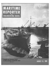
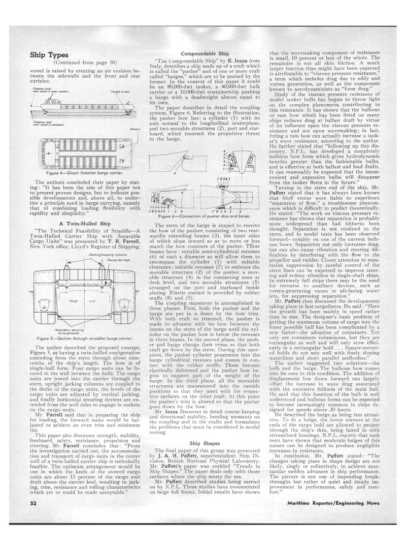
Ship Types (Continued from page 50) vessel is raised by creating an air cushion be-tween the sidewalls and the front and rear curtains. Figure 4?Direct flototion barge carrier. The authors concluded their paper by stat-ing: "It has been the aim of this paper not to present proven designs, but to indicate pos-sible developments and, above all, to under-line a principle need in barge carrying, namely that of combining loading flexibility with rapidity and simplicity." A Twin-Hulled Ship "The Technical Feasibility of Straddle?A Twin-Hulled Carrier Ship with Separable Cargo Units" was presented by T. R. Farrell, New York office, Lloyd's Register of Shipping. Jacking/coup/ing columns rj Toeing carriage !rJ?V ^T i/ Secondary securing arrangements Figure 5?Section through straddler barge carrier. The author described the proposed concept, Figure 5, as having a twin-hulled configuration extending from the stern through about nine-tenths of the ship's length. The bow is of single-hull form. Four cargo units can be lo-cated in the well between the hulls. The cargo units are towed into the carrier through the stern, upright jacking columns are coupled to the decks of the cargo units, the levels of the cargo units are adjusted by vertical jacking, and finally horizontal securing devices are ex-tended from the well sides to engage in sockets on the cargo units. Mr. Farrell said that in preparing the ship for loading, the forward tanks would be bal-lasted to achieve an even trim and minimum list. This paper also discusses strength, stability, freeboard, safety, resistance, propulsion and steering. Mr. Farrell concludes that: "From the investigation carried out, the accommoda-tion and transport of cargo units in the center well of a twin-hulled carrier ship is technically feasible. The optimum arrangement would be one in which the keels of the stowed cargo units are about 15 percent of the cargo unit draft above the carrier keel, resulting in jack-ing, trim, resistance and rolling characteristics which are or could be made acceptable." Compoundable Ship "The Compoundable Ship" by E. Iozza from Italy, describes a ship made up of a craft which is called the "pusher" and of one or more craft called "barges," which are to be pushed by the former. In the context of this paper it could be an 80,000-dwt tanker, a 40,000-dwt bulk carrier or a 10,000-dwt containership pushing a barge with a deadweight almost equal to its own. The paper describes in detail the coupling system, Figure 6. Referring to the illustration, the pusher bow has: a cylinder (1) with its axis normal to the longitudinal centerplane, and two movable structures (2), port and star-board, which transmit the propulsive thrust to the barge. 7B'2a5 9 1 Figure 6-7 e' z a j Connection of pusher ship and barge. The stern of the barge is shaped to receive the bow of the pusher, consisting of two rear-wardly extending beams (3), the inner sides of which slope inward so as to more or less match the bow contours of the pusher. These beams have: suitable semi-cylindrical recesses (6) of such a diameter as will allow them to encompass the cylinder (1) with suitable clearance; suitable recesses (7) to embrace the movable structure (2) of the pusher, a mov-able structure (4) in the connecting zone at deck level, and two movable structures (5) arranged on the port and starboard inside plating. Elastic contact is provided by rubber muffs (8) and (9). The coupling maneuver is accomplished in three phases. First, both the pusher and the barge are put in a down by the bow trim. With both craft so trimmed, the pusher is made to advance with its bow between the beams on the stern of the barge until the cyl-inder on the pusher bow is below the recesses in these beams. In the second phase, the push-er and barge change their trims so that both craft go down by the stern. During this oper-ation, the pusher cylinder penetrates into the barge cylindrical recesses and comes in con-tact with the rubber muffs. These become elastically deformed and the pusher bow be-gins to support part of the weight of the barge. In the third phase, all the moveable structures are maneuvered into the outside positions so that they meet with the respec-tive surfaces on the other craft. At this point the pusher's trim is altered so that the pusher goes down by the bow. Mr. Iozza discusses in detail course keeping and directional stability, bending moments on the coupling and in the crafts and formulates the problems that must be considered in model testing. Ship Shapes The final paper of this group was presented by J. A. H. Paffett, superintendent, Ship Di-vision, British National Physical Laboratory. Mr. Paffett's paper was entitled "Trends in Ship Shapes." The paper deals only with those surfaces where the ship meets the sea. Mr. Paffett described studies being carried on by N.P.L. These studies have concentrated on large full forms. Initial results have shown that the wavemaking component of resistance is small, 10 percent or less of the whole. The remainder is not all skin friction. A much larger fraction than might have been expected is attributable to "viscous pressure resistance," a term which includes drag due to eddy and vortex generation, as well as the component known to aerodynamicists as "form drag." Study of the viscous pressure resistance of model tanker hulls has begun to throw light on the complex phenomena contributing to this resistance. It has shown that the bulbous or ram bow which has been fitted on many ships reduces drag at ballast draft by virtue of its influence upon the viscous pressure re-sistance and not upon wavemaking; in fact, fitting a ram bow can actually increase a tank-er's wave resistance, according to the author. He further stated that "following up this dis-covery, N.P.L. has developed a completely bulbless bow form which gives hydrodynamic benefits greater than the fashionable bulbs, and is effective at both ballast and load drafts. It can reasonably be expected that the incon-venient and expensive bulbs will disappear from the tanker fleets in the future." Turning to the stern end of the ship, Mr. Paffett stated that it has always been known that bluff sterns were liable to experience "separation of flow," a troublesome phenom-enon which is difficult to predict theoretically. He stated: "The work on viscous pressure re-sistance has shown that separation is probably more widespread than had hitherto been thought. Separation is not confined to the stern, and in model tests has been observed forward?notably on one of the current bulb-ous bows. Separation not only increases drag, but can also cause vibration and steering dif-ficulties by interfering with the flow to the propeller and rudder. Closer attention to sepa-ration suppression by careful control of the stern lines can be expected to improve steer-ing and reduce vibration in single-shaft ships. In extremely full ships there may be the need for recourse to auxiliary devices, such as vortex-generating vanes or aft-facing water jets, for suppressing separation." Mr. Paffett then discussed the developments taking place in fast cargoliners. He said : "Here the growth has been mainly in speed rather than in size. The designer's basic problem of getting the maximum volume of cargo into the finest possible hull has been complicated by a new factor?the adoption of containers. Not only are containers voluminous, but they are rectangular as well and will only stow effici-ently in a rectangular hold . . . Square-corner-ed holds do not mix well with finely sloping waterlines and short parallel midbodies." The author suggested two solutions?the bulb and the bulge. The bulbous bow comes into its own in this condition. The addition of displacement low down forward can largely offset the increase in wave drag associated with the excessive fullness of the main hull. He said that this function of the bulb is well understood and bulbous forms can be expected to become increasingly common in ships de-signed for speeds above 20 knots. He described the bulge as being less attrac-tive. To fit a bulge, the lower corners at the ends of the cargo hold are allowed to project through the ship's skin, being faired in with streamlined housings. N.P.L. reports that tank tests have shown that moderate bulges of this nature can be designed to produce negligible increases in resistance. In conclusion, Mr. Paffett stated: "The changes taking place in shape design are not likely, singly or collectively, to achieve spec-tacular sudden advances in ship performance. The picture is not one of impending break-throughs but rather of quiet and steady im-provement in performance, safety and com-fort." /m/ whtn vessel in movement curtain 52 Maritime Reporter/Engineering News
