Page 6: of Maritime Reporter Magazine (March 1971)
Read this page in Pdf, Flash or Html5 edition of March 1971 Maritime Reporter Magazine
 5
5
 7
7
Engineer's control console and alarm panel. bly point, while labor was reasonably fixed at one location to allow repetitive operations.
The shipyard technical staff developed in- novative techniques for handling, moving and aligning modules.
Throughout the module fabrication, align- ment of module to module and midbody to bow and stern, a Laser theodolite was used.
The red Laser beam aligned on a desired refer- ence point throws a point of red light on the target. Moving the structure with its attached target until the point of light is properly lo- cated on the target brings the unit into proper alignment. Theoretically, the structure can be located to within 1/16 of an inch. Practically, the limits are greater and depend to some de- gree on the structure being aligned and out- side influences such as wind. Unloading equip- ment tolerances required that the longitudinal centerlines of the bow, each module and the stern fall within a zone inch each side of the vessel's centerline regardless of whether the offset of the centerline was caused by hori- zontal or angular misalignment.
The midship structure was developed almost entirely on the basis of the shipyard manufac- turing process. Because of the development of a procedure to use electro-gas welding effec- tively for seam welds it allowed the choosing of a narrower basic plate width as a building block than would normally have been the case.
The 90-inch width is the maximum width that can be purchased maintaining the minimum add-on unit costs for width.
The conventional transverse side framing and transverse stiffener arrangement on the cargo-hold slopes was revised to longitudinal framing to suit the panel welding machine production. Dishing of the cargo-hold slopes between stiffeners in a direction that would restrict the flow of the cargo dregs was a con- sideration motivating against the use of longi- tudinal cargo-hold stiffening but it was felt to be less of a problem with the pellet cargo than with an all-purpose carrier. Considerable sub- jective discussion took place on the suspected disadvantages of longitudinal side framing versus transverse framing relative to side shell- dock damage. The closely spaced longitudinals and the heavy transverse webs appeared to provide equal shell support and production be- came the controlling consideration.
No riveted seams are used as crack arresters.
Instead a grade EH plate is used at the bilge and gunwale; they are normalized after form- ing and carried a minimum of 6 feet onto the deck and bottom shell.
Cargo-hold slopes and hogbacks were plated with a 50,000 psi yield steel to gain a slightly higher Brinell than was available with mild steel for improved abrasion resistance.
The upper and lower flanges of the hull girder were made of higher strength steels to gain a 1,000-long-ton deadweight improvement.
Because of the wide hatch spacing (48 feet), the high strength materials were used between the hatches on the assumption that the stress lines would enter this area to some degree and
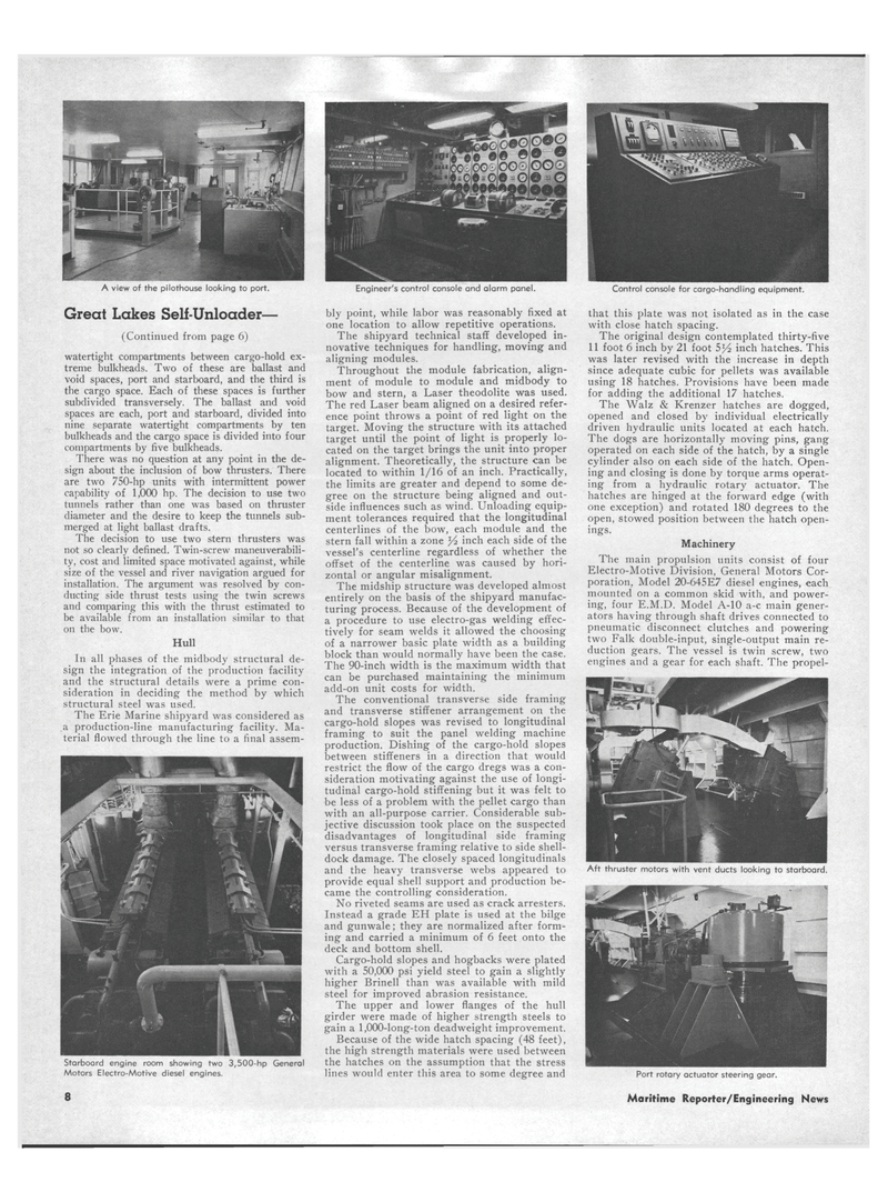
A view of the pilothouse looking to port.
Great Lakes Sell-Unloader— (Continued from page 6) watertight compartments between cargo-hold ex- treme bulkheads. Two of these are ballast and void spaces, port and starboard, and the third is the cargo space. Each of these spaces is further subdivided transversely. The ballast and void spaces are each, port and starboard, divided into nine separate watertight compartments by ten bulkheads and the cargo space is divided into four compartments by five bulkheads.
There was no question at any point in the de- sign about the inclusion of bow thrusters. There are two 750-hp units with intermittent power capability of 1,000 hp. The decision to use two tunnels rather than one was based on thruster diameter and the desire to keep the tunnels sub- merged at light ballast drafts.
The decision to use two stern thrusters was not so clearly defined. Twin-screw maneuverabili- ty, cost and limited space motivated against, while size of the vessel and river navigation argued for installation. The argument was resolved by con- ducting side thrust tests using the twin screws and comparing this with the thrust estimated to be available from an installation similar to that on the bow.
Hull
In all phases of the midbody structural de- sign the integration of the production facility and the structural details were a prime con- sideration in deciding the method by which structural steel was used.
The Erie Marine shipyard was considered as a production-line manufacturing facility. Ma- terial flowed through the line to a final assem-
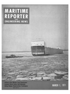
Starboard engine room showing two 3,500-hp General
Motors Electro-Motive diesel engines. 8
Control console for cargo-handling equipment. that this plate was not isolated as in the case with close hatch spacing.
The original design contemplated thirty-five 11 foot 6 inch by 21 foot 5y2 inch hatches. This was later revised with the increase in depth since adequate cubic for pellets was available using 18 hatches. Provisions have been made for adding the additional 17 hatches.
The Walz & Krenzer hatches are dogged, opened and closed by individual electrically driven hydraulic units located at each hatch.
The dogs are horizontally moving pins, gang operated on each side of the hatch, by a single cylinder also on each side of the hatch. Open- ing and closing is done by torque arms operat- ing from a hydraulic rotary actuator. The hatches are hinged at the forward edge (with one exception) and rotated 180 degrees to the open, stowed position between the hatch open- ings.
Machinery
The main propulsion units consist of four
Electro-Motive Division, General Motors Cor- poration, Model 20-645E7 diesel engines, each mounted on a common skid with, and power- ing, four E.M.D. Model A-10 a-c main gener- ators having through shaft drives connected to pneumatic disconnect clutches and powering two Falk double-input, single-output main re- duction gears. The vessel is twin screw, two engines and a gear for each shaft. The propel-
Aft thruster motors with vent ducts looking to starboard.
Port rotary actuator steering gear.
Maritime Reporter/Engineering News
