
Page 14: of Maritime Reporter Magazine (September 1971)
Read this page in Pdf, Flash or Html5 edition of September 1971 Maritime Reporter Magazine
 13
13
 15
15
Extensive Testing And Research Develop The
Turbopitch Propulsion System
A High-Speed Gas Turbine, Unigue Gear Box And CRP Propeller Are
Combined To Provide Reliability For Offshore Supply/Tug Vessels
Ronald G. Hall, John K. Liu, and T.B. Lauriat*
The mode of transportation for offshore supply/tug vessels dictates that speed and reliability are the two most important prerequisites.
Since the weight of the propul- sion system would have an impor- tant influence on the speed, range and payload, it was decided to use a lightweight gas-turbine prime mover, a lightweight reduction gear box and a controllable-reversi- ble-pitch propeller. This led to the development of the "Turbopitch" propulsion system.
This propulsion system is de- signed with two configurations: 1. Straight drive where the prime mover is mounted forward of the gear box, and 2. "U" drive where the prime mover is mounted aft of the gear box and over the propeller shaft.
As the type, size and speed of the vessels would vary consider- ably, it was decided to standardize as much as possible and keep to a minimum the different sizes of the major components. The system was developed primarily for horse- powers from 1,000 to 2,500. This appeared to meet the requirements of owners who operated medium and high-speed vessels from 75 feet to 120 feet in length and speeds from 25 knots to 40 knots with sin- gle or twin-screw configurations.
The speed of the propeller was another variable. This could vary between 900 rpm and 1,400 rpm.
The propeller speed selected as the most suitable was 1,200 rpm.
The final range of sizes selected were 1.000 hp, 1,250 hp, 2,000 hp and 2,500 hp. This range required two different sizes of propeller hubs and reduction gear boxes and four sizes of gas turbines.
Propeller
The controllable reversible pro- peller ('CRP) is of A.M. Liaaen
A/S, Aalesund, Norway, design.
This particular type of propeller has been tested and proven since 1962 when Kongsberg Vapenfab- rikk was involved in a project to evaluate the marine application of a 500-hp gas turbine. This project involved building a 32-foot single- screw vessel, the Rimfakse.
This project at its inception had a fixed-pitch propeller system.
However, due to the problems in
Obtaining a reliable lightweight re- duction gear for a high-speed ma- rine turbine A.M. Liaaen was con- sulted to design a prototype CRP propeller so that the advantages of the lightweight high-speed features of the gas turbine could be utilized.
The KV-AML high-speed pro- peller system represented an ad- vance in marine propulsion as it contained a number of new tech- nical solutions enabling the system to operate relialbly and efficiently under high loadings and rpms.
The propeller system consists of an oil-control box, shaft, hub-blade assembly and a reduction gear 'box.
The blades have super-cavitating sections which were developed after intensive model tank testing.
Despite the fact that such sections are optimized for operation from around 40 knots and above, the propeller demonstrated very good efficiency all the way to the lowest speeds.
The initial 50-hour test program proved the propeller system to be smooth in operation and continu- ous control was achieved at all power levels.
The test demonstrated that in conjunction with a free-power tur- bine. variable pitch should not be resorted to as means of speed con- trol under normal operation. The optimum pitch angle was approxi- mately constant from 5 to 32 knots, and this angle gave at any forward speed the highest propeller per- formance and the lowest fuel con- sumption.
In comparison with a similar prototype gas-turbine-powered ves- sel employing a conventional fixed- pitch propeller system the program showed that the KV-AML super- cavitating propeller was capable of satisfactory performance at all speed levels.
Conventional cavitation erosion was present, but to a lesser extent than anticipated. The propeller was, cavitation wise, suitable at all speed levels.
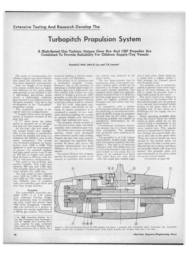
The propeller is of A.M. Liaaen three-bladed, double-crank design with servomotor located in the hub,
Figure 1. The hub is of corrosion resistant steel. The blades also are of corrosion-resistant steel and are each bolted to the crank disc by means of six stainless-steel bolts.
The crank discs are each fitted with two crank pins located oppo- site of each other. Each crank pin is fitted with a slipper which is held between the forward piston and the guide block.
The propeller hub is completely sealed to prevent water from enter- ing or oil from leaking out. The hub is under oil pressure from a head tank located in the vessel.
The servo control box, Figure 2, is mounted on the forward side of the reduction-gear box. Its purpose is to transmit pitch-control handle motion to the spool valve in the propeller hub. It also serves as a distributor for the supply and ex- haust oil.
When operating propeller pitch from the control stand, the handle travel or pitch called for on the control stand is transmitted to the control handle on the side of the servo control box. This angular motion is transferred to linear mo- tion through the control-shaft slip- per to the yoke to the spool valve.
When the control handle has been moved to the desired pitch, the spool valve will take a center posi- tion and the servo piston and hence the propeller blades will stop their motion. The propeller pitch will now correspond to the pitch called for on the control handle. (Continued on page 18) * Mr. Hall, Propulsion Systems, Inc.;
Mr. Liu, Philadelphia Gear Corporation, and Mr. Lauriat, Avco Lycoming Divi- sion, presented the paper condensed here before the recent Offshore Tech- nology Conference held in Dallas, Tex. Figure 1—The cross sectional view of the CRP propeller hub shows: 1-propeller hub, 2-propeller shaft, 3-fairwater cap, 4-propeller blade, 5-crank disc, 6-crankpin, 7-forward piston, 8-aft piston, 9-piston rod, 10-spool valve, and 11-oil tube. 16 Maritime Reporter/Engineering News
