
Page 28: of Maritime Reporter Magazine (January 15, 1973)
Read this page in Pdf, Flash or Html5 edition of January 15, 1973 Maritime Reporter Magazine
 27
27
 29
29
N.Y. Engineering Groups Discuss
The Power Transmission System
Installed On Euroliner Class Ships
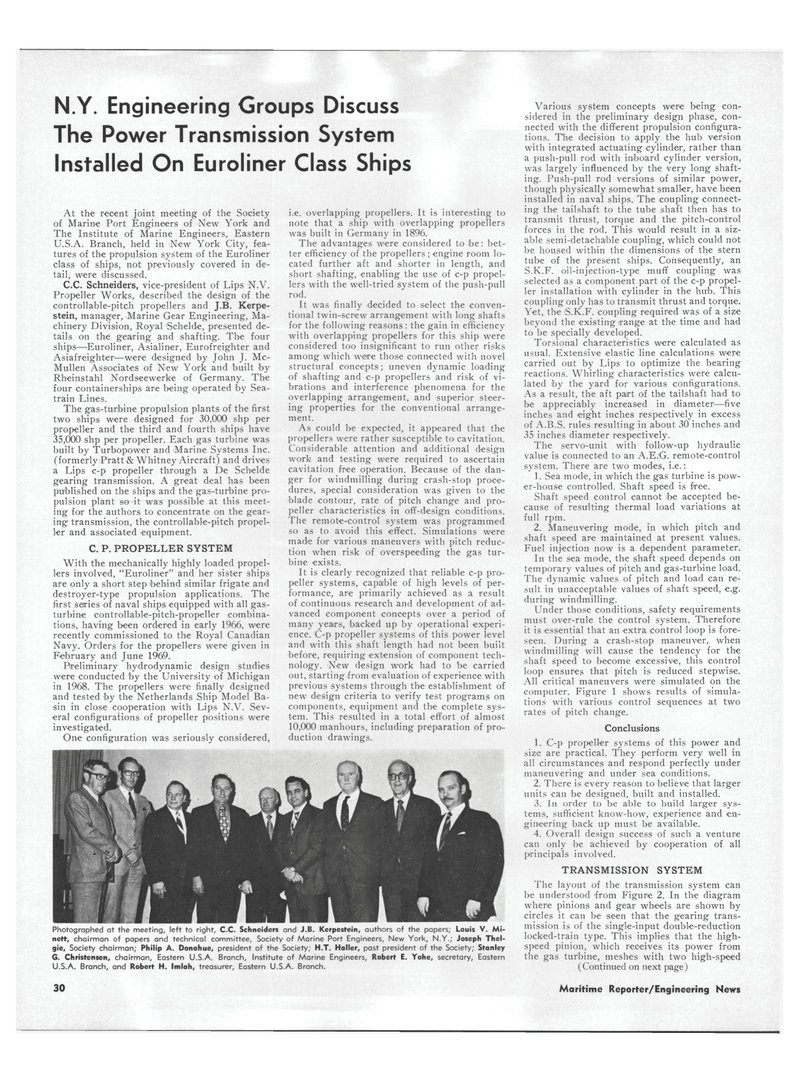
Photographed at the meeting, left to right, C.C. Schneiders and J.B. Kerpestein, authors of the papers; Louis V. Mi- neft, chairman of papers and technical committee, Society of Marine Port Engineers, New York, N.Y.; Joseph Thel- gie. Society chairman; Philip A. Donahue, president of the Society; H.T. Holler, past president of the Society; Stanley
G. Christensen, chairman, Eastern U.S.A. Branch, Institute of Marine Engineers, Robert E. Yohe, secretary, Eastern
U.S.A. Branch, and Robert H. Imlah, treasurer, Eastern U.S.A. Branch.
At the recent joint meeting of the Society of Marine Port Engineers of New York and
The Institute of Marine Engineers, Eastern
U.S.A. Branch, held in New York City, fea- tures of the propulsion system of the Euroliner class of ships, not previously covered in de- tail, were discussed.
C.C. Schneiders, vice-president of Lips N.V.
Propeller Works, described the design of the controllable-pitch propellers and J.B. Kerpe- stein, manager, Marine Gear Engineering, Ma- chinery Division, Royal Schelde, presented de- tails on the gearing and shafting. The four ships—Euroliner, Asialiner, Eurofreighter and
Asiafreighter—were designed by John J. Mc-
Mullen Associates of New York and built by
Rheinstahl Nordseewerke of Germany. The four containerships are being operated by Sea- train Lines.
The gas-turbine propulsion plants of the first two ships were designed for 30,000 shp per propeller and the third and fourth ships have 35,000 shp per propeller. Each gas turbine was built by Turbopower and Marine Systems Inc. (formerly Pratt & Whitney Aircraft) and drives a Lips c-p propeller through a De Schelde gearing transmission. A great deal has been published on the ships and the gas-turbine pro- pulsion plant so it was possible at this meet- ing foir the authors to concentrate on the gear- ing transmission, the controllable-pitch propel- ler and associated equipment.
C. P. PROPELLER SYSTEM
With the mechanically highly loaded propel- lers involved, "Euroliner" and her sister ships are only a short step behind similar frigate and destroyer-type propulsion applications. The first series of naval ships equipped with all gas- turbine controllable-pitch-propeller combina- tions, having been ordered in early 1966, were recently commissioned to the Royal Canadian
Navy. Orders for the propellers were given in
February and June 1969.
Preliminary hydrodynamic design studies were conducted by the University of Michigan in 1968. The propellers were finally designed and tested by the Netherlands Ship Model Ba- sin in close cooperation with Lips N.V. Sev- eral configurations of propeller positions were investigated.
One configuration was seriously considered, i.e. overlapping propellers. It is interesting to note that a ship with overlapping propellers was built in Germany in 1896.
The advantages were considered to be: bet- ter efficiency of the propellers ; engine room lo- cated further aft and shorter in length, and short shafting, enabling the use of c-p propel- lers with the well-tried system of the push-pull rod.
It was finally decided to select the conven- tional twin-screw arrangement with long shafts for the following reasons: the gain in efficiency with overlapping propellers for this ship were considered too insignificant to run other risks among which were those connected with novel structural concepts; uneven dynamic loading of shafting and c-p propellers and risk of vi- brations and interference phenomena for the overlapping arrangement, and superior steer- ing properties for the conventional arrange- ment.
As could be expected, it appeared that the propellers were rather susceptible to cavitation.
Considerable attention and additional design work and testing were required to ascertain cavitation free operation. Because of the dan- ger for windmilling during crash-stop proce- dures, special consideration was given to the blade contour, rate of pitch change and pro- peller characteristics in off-design conditions.
The remote-control system was programmed so as to avoid this effect. Simulations were made for various maneuvers with pitch reduc- tion when risk of overspeeding the gas tur- bine exists.
It is clearly recognized that reliable c-p pro- peller systems, capable of high levels of per- formance, are primarily achieved as a result of continuous research and development of ad- vanced component concepts over a period of many years, backed up by operational experi- ence. C-p propeller systems of this power level and with this shaft length had not been built before, requiring extension of component tech- nology. New design work had to be carried out, starting from evaluation of experience with previous systems through the establishment of new design criteria to verify test programs on components, equipment and the complete sys- tem. This resulted in a total effort of almost 10,000 manhours, including preparation of pro- duction drawings.
Various system concepts were being con- sidered in the preliminary design phase, con- nected with the different propulsion configura- tions. The decision to apply the hub version with integrated actuating cylinder, rather than a push-pull rod with inboard cylinder version, was largely influenced by the very long shaft- ing. Push-pull rod versions of similar power, though physically somewhat smaller, have been installed in naval ships. The coupling connect- ing the tailshaft to the tube shaft then has to transmit thrust, torque and the pitch-control forces in the rod. This would result in a siz- able semi-detachable coupling, which could not be housed within the dimensions of the stern tube of the present ships. Consequently, an
S.K.F. oil-injection-type muff coupling was selected as a component part of the c-p propel- ler installation with cylinder in the hub. This coupling only has to transmit thrust and torque.
Yet, the S.K.F. coupling required was of a size beyond the existing range at the time and had to be specially developed.
Torsional characteristics were calculated as usual. Extensive elastic line calculations were carried out by Lips to optimize the bearing reactions. Whirling characteristics were calcu- lated by the yard for various configurations.
As a result, the aft part of the tailshaft had to be appreciably increased in diameter—five inches and eight inches respectively in excess of A.B.S. rules resulting in about 30 inches and 35 inches diameter respectively.
The servo-unit with follow-up hydraulic value is connected to an A.E.G. remote-control system. There are two modes, i.e.: 1. Sea mode, in which the gas turbine is pow- er-house controlled. Shaft speed is free.
Shaft speed control cannot be accepted be- cause of resulting thermal load variations at full rpm. 2. Maneuvering mode, in which pitch and shaft speed are maintained at present values.
Fuel injection now is a dependent parameter.
In the sea mode, the shaft speed depends on temporary values of pitch and gas-turbine load.
The dynamic values of pitch and load can re- sult in unacceptable values of shaft speed, e.g. during windmilling.
Under those conditions, safety requirements must over-rule the control system. Therefore it is essential that an extra control loop is fore- seen. During a crash-stop maneuver, when windmilling will cause the tendency for the shaft speed to become excessive, this control loop ensures that pitch is reduced stepwise.
All critical maneuvers were simulated on the computer. Figure 1 shows results of simula- tions with various control sequences at two rates of pitch change.
Conclusions 1. C-p propeller systems of this power and size are practical. They perform very well in all circumstances and respond perfectly under maneuvering and under sea conditions. 2. There is every reason to believe that larger units can be designed, built and installed. 3. In order to be able to build larger sys- tems, sufficient know-how, experience and en- gineering back up must be available. 4. Overall design success of such a venture can only be achieved by cooperation of all principals involved.
TRANSMISSION SYSTEM
The layout of the transmission system can be understood from Figure 2. In the diagram where pinions and gear wheels are shown by circles it can be seen that the gearing trans- mission is of the single-input double-reduction locked-train type. This implies that the high- speed pinion, which receives its power from the gas turbine, meshes with two high-speed (Continued on next page) 30 Maritime Reporter/Engineering News
