Page 29: of Maritime Reporter Magazine (January 15, 1973)
Read this page in Pdf, Flash or Html5 edition of January 15, 1973 Maritime Reporter Magazine
 28
28
 30
30
Power Transmission System
On Euroliner Class Ships- gear wheels, each of these driving a low-speed pinion, meshing with the low-speed gear wheel.
This arrangement of pinions and gear wheels, sometimes referred to as divided-power trans- mission or dual-torque-path transmission or dual-tandem arrangement, provides for a split up of the input power in two halves, each half being transmitted by its associated high-speed gear wheel and low-speed pinion to the low- speed gear wheel.
The advantage of this is that each tooth engagement has to transmit only half of the gear input power and accordingly pinions and gear wheels can be kept small. Although this arrangement requires one high-speed gear wheel and one low-speed pinion in excess of the number of gearing elements required for single-tooth engagement, the net effect of this division of power on the gearing transmission as a whole is that its size and weight are re- duced to a minimum.
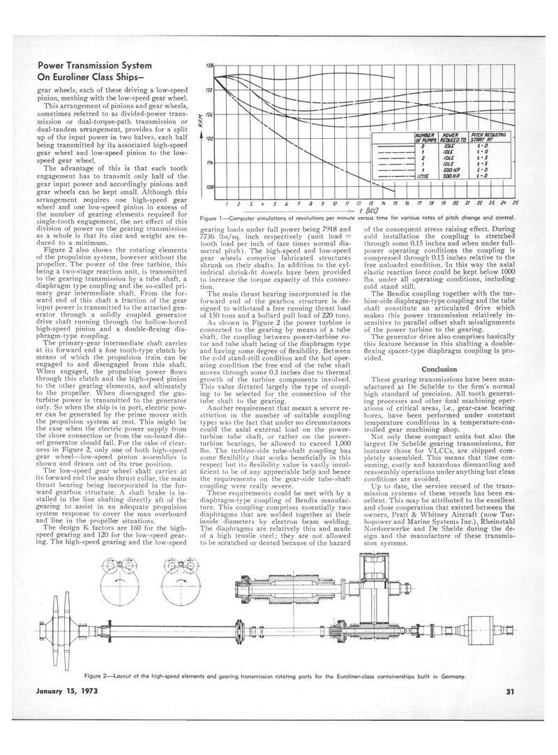
Figure 2 also shows the rotating elements of the propulsion system, however without the propeller. The power of the free turbine, this being a two-stage reaction unit, is transmitted to the gearing transmission by a tube shaft, a diaphragm type coupling and the so-called pri- mary gear intermediate shaft. From the for- ward end of this shaft a fraction of the gear input power is transmitted to the attached gen- erator through a solidly coupled generator drive shaft running through the hollow-bored high-speed pinion and a double-flexing dia- phragm-type coupling.
The primary-gear intermediate shaft carries at its forward end a fine tooth-type clutch by means of which the propulsion train can foe engaged to and disengaged from this shaft.
When engaged, the propulsive power flows through this clutch and the high-speed pinion to the other gearing elements, and ultimately to the propeller. When disengaged the gas- turbine power is transmitted to the generator only. So when the ship is in port, electric pow- er can be generated by the prime mover with the propulsion system at rest. This might be the case when the electric power supply from the shore connection or from the on-board die- sel generator should fail. For the sake of clear- ness in Figure 2, only one of both high-speed gear wheel—low-speed pinion assemblies is shown and drawn out of its true position.
The low-speed gear wheel shaft carries at its forward end the main thrust collar, the main thrust bearing being incorporated in the for- ward gearbox structure. A shaft brake is in- stalled in the line shafting directly aft of the gearing to assist in an adequate propulsion system response to cover the man overboard and line in the propellelr situations.
The design K factors are 160 for the high- speed gearing and 120 for the low-speed gear- ing. The high-speed gearing and the low-speed
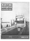
Figure 1—Computer simulations of revolutions per minute versus time for various rates of pitch change and control. gearing loads under full power being 7918 and 7736 lbs/sq. inch respectively (unit load = tooth load per inch of face times normal dia- metral pitch). The high-speed and low-speed gear wheels comprise fabricated structures shrunk on their shafts. In addition to the cyl- indrical shrink-fit dowels have been provided to increase the torque capacity of this connec- tion.
The main thrust bearing incorporated in the forward end of the gearbox structure is de- signed to withstand a free running thrust load of 150 tons and a bollard pull load of 220 tons.
As shown in Figure 2 the power turbine is connected to the gearing by means of a tube shaft, the coupling between power-turbine ro- tor and tube shaft being of the diaphragm type and having some degree of flexibility. Between the cold stand-still condition and the hot oper- ating condition the free end of the tube shaft moves through some 0.3 inches due to thermal growth of the turbine components involved.
This value dictated largely the type of coupl- ing to foe selected for the connection of the tube shaft to the gearing.
Another requirement that meant a severe re- striction in the number of suitable coupling types was the fact that under no circumstances could the axial external load on the power- turbine tube shaft, or rather on the power- turbine bearings, foe allowed to exceed 1,000 lbs. The turbine-side tube-shaft coupling has some flexibility that works beneficially in this respect but its flexibility value is vastly insuf- ficient to be of any appreciable help and hence the requirements on the gear-side tube-shaft coupling were really severe.
These requirements could foe met with by a diaphragm-type coupling of Bendix manufac- ture. This coupling comprises essentially two diaphragms that are welded together at their inside diameters by electron foeam welding.
The diaphragms are relatively thin and made of a high tensile steel; they are not allowed to be scratched or dented because of the hazard of the consequent stress raising effect. During cold installation the coupling is stretched through some 0.15 inches and when under full- power operating conditions the coupling is compressed through 0.15 inches relative to the free unloaded condition. In this way the axial elastic reaction force could be kept below 1000 lbs. under all operating conditions, including cold stand still.
The Bendix coupling together with the tur- bine-side diaphragm-type coupling and the tube shaft constitute an articulated drive which makes this power transmission relatively in- sensitive to parallel offset shaft misalignments of the power turbine to the gearing.
The generator drive also comprises basically this feature because in this shafting a double- flexing spacer-type diaphragm coupling is pro- vided.
Conclusion
These gearing transmissions have been man- ufactured at De Schelde to the firm's normal high standard of precision. All tooth generat- ing processes and other final machining oper- ations of critical areas, i.e., gear-case bearing bores, have been performed under constant temperature conditions in a temperature-con- trolled gear machining shop.
Not only these compact units but also the largest De Schelde gearing transmissions, for instance those for VLCCs, are shipped com- pletely assembled. This means that time con- suming, costly and hazardous dismantling and reassembly operations under anythingbut clean conditions are avoided.
Up to date, the service record of the trans- mission systems of these vessels has been ex- cellent. This may be attributed to the excellent and close cooperation that existed between the owners, Pratt & Whitney Aircraft (now Tur- bopower and Marine Systems Inc.), Rheinstahl
Nordseewerke and De Shelde during the de- sign and the manufacture of these transmis- sion systems.
Figure 2—Layout of the high-speed elements and gearing transmission rotating parts for the Euroliner-class containerships built in Germany.
January 15, 1973 31
