
Page 28: of Maritime Reporter Magazine (December 15, 1973)
Read this page in Pdf, Flash or Html5 edition of December 15, 1973 Maritime Reporter Magazine
 27
27
 29
29
Investigation On Free and Forced
Vibrations Of An LNG Tanker With
Overlapping Propeller Arrangement
K. Restod, G.C. Volcy, H. Gamier and J.C. Masson*
Economic imperatives are always compelling shipyards and shipown- ers to look for the most efficient solutions. One of the ways to reach this aim is to increase the total propulsive efficiency of propulsion installations. In this respect the arrangement of overlapping pro- pellers is very promising.
Since no experience existed con- cerning the vibration characteris- tics of this type of propeller ar- rangement, some investigations aimed at obtaining the values of hydrodynamic excitations and the vibratory response of the propul- sive plant and hull steelwork were undertaken. The investigations presented in this paper were car- ried out as a research project. The ship considered, a 160,000-cubic- meter LNG vessel, is not a ship on order.
The main reason for these in- vestigations was to find out wheth- er the considered ship, with rela- tively high power and the uncon- ventional overlapping-propeller ar- rangement, which from other points of view seemed to be an attractive one, could also be attrac- tive with regard to vibration and cavitation.
In addition, this type of investi- gation also was important to test the experimental facilities for the determination of hydrodynamic ex- citations as well as the available established methods of calculation.
Another interesting side of this research was to determine how to proceed with structural rearrange- ments of the steelwork of the shaft arrangement in case of eventually undesired effects due to the appli- cation of the existing excitation forces.
As it was not necessary to have very detailed information on this particular vessel, and in order to save time, some simplifications have been admitted in the experi- mental determination of excita- *Mr. Rest-ad, naval architect and ma- rine engineer, Kockums Mekaniska
Verkstads Ab Malmoe; Mr. Vpley, prin- cipal engineer, Special Research and
Study Section of Maritime Services of
Bureau Veritas; Mr. Gamier, principal engineer. Special Research and Study
Section of Maritime Services of Bureau
Veritas, and Mr. Masson, engineer, Spe- cial Research and Study Section of
Maritime Services of Bureau Veritas, presented the paper abstracted here be- fore the recent Annual Meeting of The
Society of Naval Architects and Marine
Engineers. tions, for instance, by not paying too much attention to an absolute- ly correct wake distribution in the cavitation tunnel.
The investigations consisted of two main parts: (1) Experimental determination of the values of hy* drodynamic excitations, and (2)
Calculations of the response in free and forced vibrations of the propul- sive plant and the steelwork of the vessel to the determined excita- tions.
It may be useful to clarify the opinion of the authors regarding the real hydrodynamic excitations and the vibratory phenomena oc- curring on ships.
First, decisions were made con- cerning: vessel speed, propulsive plant power, propeller rpm, type and geometry of propellers, num- ber of propeller blades, and corre- sponding stern arrangement and geometry of the body of the aft part of the vessel.
Then real hydrodynamic excita- tions are given. In fact, both types of hydrodynamic excitations, (a) the variation of six components of propeller forces, and (b) the full surface forces, having their origin in the action of the propeller in the non-uniform wake field, are functions of the previously men- tioned parameters. Their numeri- cal evaluation can be obtained ei- ther on the basis of 'theoretical cal- culations, or from model tests in a conveniently equipped towing tank and cavitation tunnel.
To obtain as reliable as possible values of hydrodynamic excita- tions, we used the experimental technique developed by the Neth- erlands Ship Model Basin (NSMB) in Wageningen. With regard to the vibratory behavior of the ves- sel, what is of utmost importance is the response to the given exist- ing excitations, of the elastic sys- tems constituted by the line shaft- ing and propulsive plant and the steelwork of the engine room and hull girder together with append- ages.
The responsibility of the engi- neers in charge of vibration analy- sis consists in avoiding the dynam- ic amplification of the given exist- ing excitations due to the eventual resonant response of one or several previously mentioned elastic sys- tems to the excitations present.
Shipboard and theoretical in- vestigations of the commonly call- ed ship vibration have led the authors to conclude that for today's huge vessels the main problem is not the free vibrations of the hull girder, with the exception of springing and whipping phenom- ena, but the forced vibration of the different partial elastic systems of the steelwork which occur when the so-called forced-vibration reso- nators are situated in way of the propulsive plant shafting, i.e., main- ly in the engine room.
The vibration analysis can be subdivided into three steps: 1. To research the forced-vibra- tion resonators which may be of two types, active and passive; 2. In case of their presence, to attempt to detune them by shifting their natural frequencies the far- thest possible from the nearest ex- citation frequency, in order to di- minish the dynamic amplification previously mentioned, and 3. To calculate the response in forced vibrations of the elastic sys- tems present to the previously de- termined numerical values of ex- citations.
It also is worth mentioning that the approach adopted for the vi- bration analysis concerning the investigation of the response in forced vibration of the engine room is also very useful for the integral analysis of static and dynamic phenomena concerning the propul- sive plant as well as the assembly of the steelwork outside the engine room. In fact, by the convenient three-dimensional modeling, calling for the finite-element technique of the engine room steelwork, this elastic model allows one to: 1. Determine the deformations of the corresponding structure due to loading and sea conditions, hence the possibility of preparing conve- nient alignment operations of the line shafting and of investigating the influences on the static condi- tions of the propulsive plant and its shafting of the aforesaid de- formations, and 2. Determine the flux of excita- tions in way of the extremities of the engine room, which can be afterwards used for the vibratory analysis of the response in forced vibration of the steelwork in the cargo holds, or in tanks, to the ex- citation flux.
The main particulars of the con- sidered LNG carrier are:
Length, overall 322,200 m
Length bet. perpendiculars 315,000 m
Breadth, molded 43.000 m
Depth, molded 30,846 m
Draft 11,887 m
Capacity of cargo tanks 160,000 cum
The machinery proposed is one
Kockums-Laval geared-steam tur- bine, type APO-61, developing 30,500 shp at 100 rpm per shaft.
The port propeller would have a diameter of 7.27 m and pitch ratio of 1.053. The starboard propeller would have a diameter of 7.27 m and a pitch ratio of 1.106. The serv- ice speed would be 23 knots.
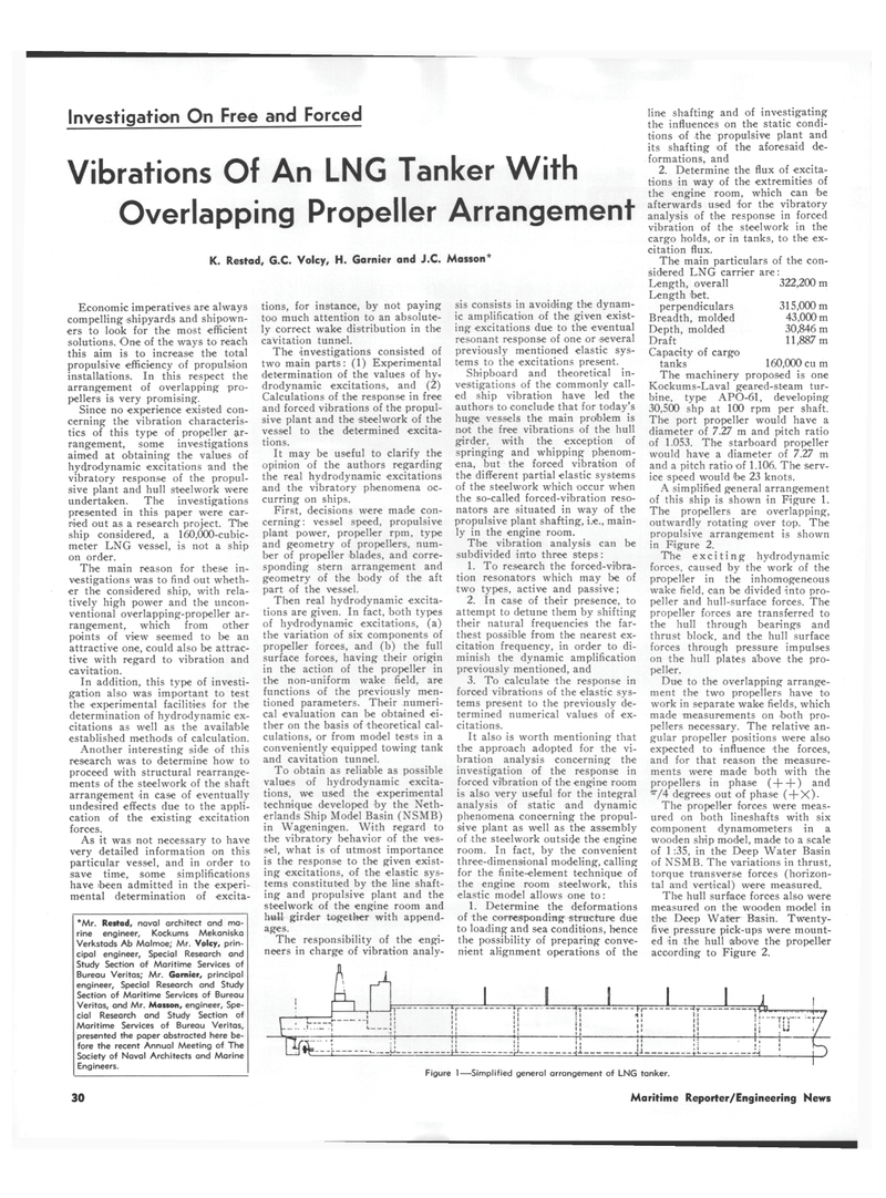
A simplified general arrangement of this ship is shown in Figure 1.
The propellers are overlapping, outwardly rotating over top. The propulsive arrangement is shown in Figure 2.
The exciting hydrodynamic forces, caused by the work of the propeller in the inhomogeneous wake field, can be divided into pro- peller and hull-surface forces. The propeller forces are transferred to the hull through bearings and thrust block, and the hull surface forces through pressure impulses on the hull plates above the pro- peller.
Due to the overlapping arrange- ment the two propellers have to work in separate wake fields, which made measurements on both pro- pellers necessary. The relative an- gular propeller positions were also expected to influence the forces, and for that reason the measure- ments were made both with the propellers in phase (+ + ) and ,r/4 degrees out of phase ( + X)-
The propeller forces were meas- ured on both lineshafts with six component dynamometers in a wooden ship model, made to a scale of 1 :35, in the Deep Water Basin of NSMB. The variations in thrust, torque transverse forces (horizon- tal and vertical) were measured.
The hull surface forces also were measured on the wooden model in the Deep Water Basin. Twenty- five pressure pick-ups were mount- ed in the hull above the propeller according to Figure 2.
X
I 1 1 I 1 < . • • i i ! ... .. -ry i 1 ' ' ! i !U J 1 '1 !, !1 I • ^ • o !l 1 • • ;! . j f 1 " 1 1 • ! r—\
Figure 1—Simplified general arrangement of LNG tanker. 30 Maritime Reporter/Engineering News
