
Page 29: of Maritime Reporter Magazine (December 15, 1973)
Read this page in Pdf, Flash or Html5 edition of December 15, 1973 Maritime Reporter Magazine
 28
28
 30
30
During the measurements in the cavitation tunnel the cavitation on the propellers also was dbserved.
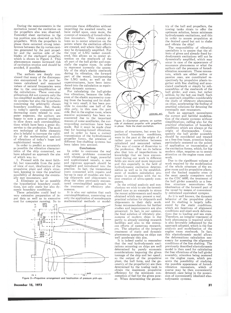
Extended sheet cavitation in the top position was observed on both propellers. With the propellers in phase there occurred strong inter- ference between the tip vortex cavi- ties generated by the port propel- ler and the suction side of the blades of the starboard propeller, which is shown in Figure 3. This phenomenon causes increased risk of cavitation erosion and should be avoided, if possible.
Calculations
The authors are deeply con- vinced that many of the discrepan- cies encountered in the past be- tween calculated and measured values of natural frequencies were due to the over-simplification of the calculations. These over-sim- plifications did not concern only the too-simplified modeling of the elas- tic systems but also the hypothesis concerning the arbitrarily chosen boundary conditions. But, thanks to today's speedy computers and decreasing costs related to com- puter expenses, the authors are happy to note a general tendency to slow down such oversimplifica- tions which have been a great dis- service to the profession. The mod- ern technique of finite elements also is helpful to increase the valid- ity of the mathematical analysis of vibrations of today's huge and sophisticated vessels.
In order to predict as accurately as possible the vibration character- istics of 'the ship concerned, we have adopted an approach the aim of which was to: 1. Proceed with the most faith- ful, but reasonable from the point of view of cost, idealization of the propulsive plant and ship's struc- ture, keeping in view the prac'tical possibility of detuning the eventu- ally met resonators; and 2. Eliminate as far as possible the hypothetical boundary condi- tions, not only static but also dy- namic boundary conditions.
These principles could lead to very extensive preparation of in- put data as well as to excessive cost for computer running. So to
U 6875 f>'2§ | overcome these difficulties without imperiling the awaited results, we have called upon, once more, the concept of research of forced-vibra- tion resonators. This concept al- lows us to center attention on the points where the excitation efforts are created, and where their effects may be dynamically amplified. For the type of LNG tanker consid- ered, this allows us to center at- tention on the steelwork of the aft part of the hull girder and espe- cially the engine room. In order to represent correctly the assem- bly of the ship's elastic steelwork during its vibration, the forward part of the vessel, incorporating the LNG tanks, as well as the superstructures, have been intro- duced into the calculation as equiv- alent dynamic systems.
For calculating the hull-girder free vibrations, because the influ- ence of the elastic asymmetry com- ing from the bossing and its shaft- ing is very small, it has been pos- sible to consider one half of the ship only, in this case the port side. But in the engine room, where massive asymmetry has been en- countered due to the important masses of some auxiliaries, the cor- responding corrections have been made. But it must be made clear that for bossing-forced vibrations, and in order to have a correct transmission of the hydrodynamic propeller forces, the presence of different Line-shafting systems has been taken into account.
Conclusions
In order to overcome the real and severe problems connected with vibrations of huge, powerful and sophisticated vessels, a new and rigorous approach should be imagined and introduced into the practice. In fact, the tremendous costs connected with repairs and lay-up in case of troubles are forc- ing shipyards and shipowners to .drop the often previously encoun- tered oversimplified approach to the treatment of vibratory phe- nomena.
It is also our opinion that such oversimplifications, concerning not only the application of nonadequate mathematical methods or model-
Figure 2—Propulsive arrangement and localization of pressure pick-ups.
LOOKING AFT.
Figure 3—Cavitation patterns on suction side of starboard propeller with propellers in phase. Note the sheet cavitation. ization of structures, but even hy- pothetical boundary conditions, were in the past a't the origin of a rather poor correlation between calculated and measured values. ,This was of course of disservice to the profession. But we do believe .also that lots of imperfections in knowledge that we have encoun- tered during our work in different fields are more and more improved and this especially in the field of hydrodynamic excitation determi- nation as well as in the establish- ment of modern calculation pro- grams in connection with the re- cent creation of ultra-speedy com- puters.
In the critical analysis and con- clusions we wish to use the investi- gated case as an example to stress the recent achievements and results obtained which may present a real, .practical solution for shipyards and shipowners in their daily work.
Some recommendations for further studies and improvements are also presented. In fact, in our opinion, the final solution of vibratory phe- nomena of modern ships is due partly to already"existing research facilities and also to the strenu- ous efforts of numerous research- ers. The adoption of the integral treatment of static and dynamic phenomena appearing on ships can well accelerate this aim.
It is indeed useful to remember that the real hydrodynamic exci- tations occurring on ships are well determined by purely economic considerations imposing the given tonnage of the ship and her speed; so the output of the propulsive plant, the hull form, and the ge- ometry of the propeller(s) are then determined by the towing tank to obtain the maximum propulsive efficiency for the minimum con- sumption of fuel for the given pow- er. When determining the geome- try of the hull and propellers, the towing tanks strain to offer the optimum Solution, hence minimum hydrodynamic excitations, and this in order to assure propulsion at the desired speed but not to shake •and vibrate the ship!
The responsibility of vibration specialists is to assure that the ef- fects of given and already fixed hy- drodynamic excitations wtill not be dynamically amplified, which may occur in case of the appearance of resonance phenomena or what the authors call the presence of forced- vibration resonators. These resona- tors, which are either active or passive ones, are constituted re- spectively by propulsive plants to- gether with line shafting and asso- ciated steelwork or simply by sub- assemblies of the steelwork of the hull girder, and even, but rather seldom, by the last one itself. Such an approach simplifies considerably the study of vibratory phenomena on ships, accelerating the finding of prac'tical solutions for detuning the eventually met resonators.
Such an approach necessitates the correct and faithful modeliza- ition of the elastic systems without simplifications, calling also for the practical elimination of boundary conditions which are always at the origin of discrepancies. Conse- quently the hull girder assembly should be considered and treated as a free-free beam, attention being particularly centered on the points of application or transmission of •the excitation forces, which, for big modern ships, requires us to center attention on the engine room steel- work.
Due to the significant volume of work required by the modelization of the whole structure of the en- gine room and its propulsive plants, and the limited capacity even of the most speedy computers such as the CDC 6600, the treatment of the hull girder assembly as a free- free structure necessitates the idealization of the forward part of the vessel by means of convenient- ly calculated equivalent systems.
As it is well known, the dynamic behavior of the propulsive plant and its shafting is largely influ- enced by the static conditions, which are functions of alignment conditions and steel-work deforma- tions due to loading and sea state.
Therefore, an integral treatment of both phenomena is required which is also favorably influenced by the approach adopted, -which is the fine analysis and modelization of the engine room steelwork. In fact, this elastodynamic model allows the deformations calculation nec- essary for assessing the alignment conditions of the line shafting. The previously described elastodynamic model is then used for calculating the free vibrations of 'the hull girder assembly, attention being centered on the engine room, which pre- sents the possibility of studying the possible appearance of forced- vibration resonators, which of course may be then conveniently detuned, once being in the posses- sion of conveniently idealized elas- todynamic systems.
December 15, 1973 31
