
Page 6: of Maritime Reporter Magazine (January 15, 1974)
Read this page in Pdf, Flash or Html5 edition of January 15, 1974 Maritime Reporter Magazine
 5
5
 7
7
I Mo. 5 CAAGOHOLP- W-o* H9 4 CAM9H01P' |44'.o» |
A7VATW\ ATVTVAAAA'VAA/ IAAAAAA^JVAA/VAj
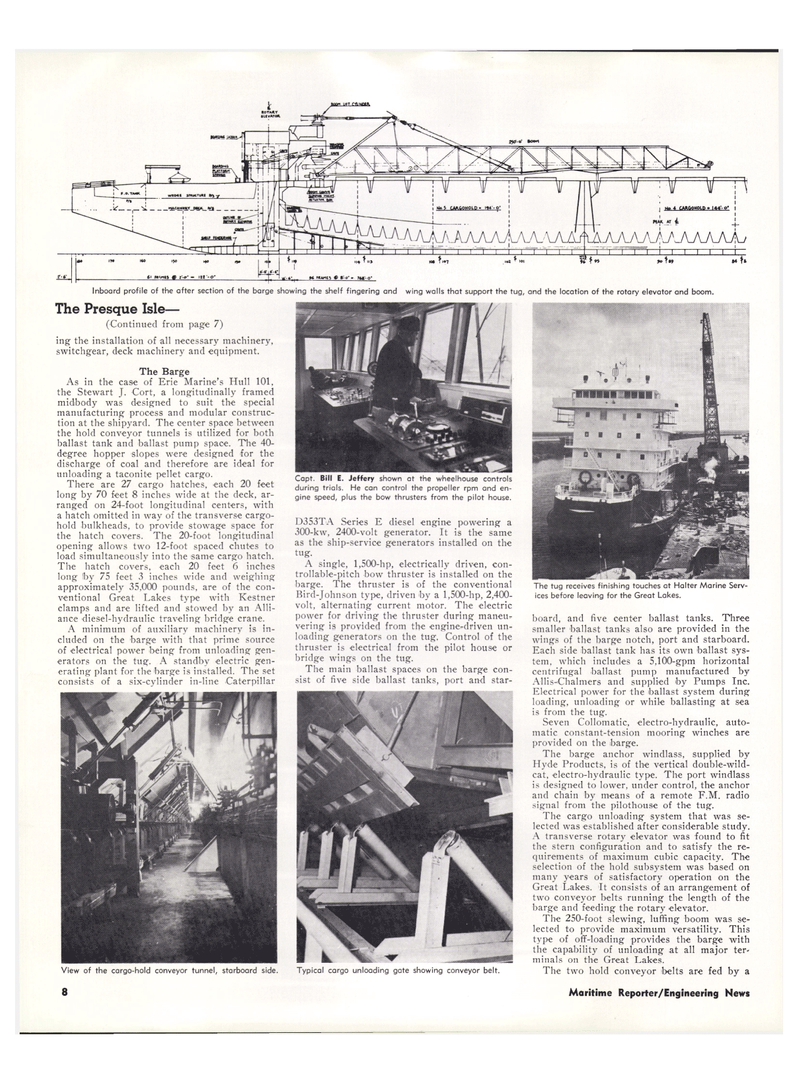
Inboard profile of the after section of the barge showing the shelf fingering and wing walls that support the tug, and the location of the rotary elevator and boom, board, and five center ballast tanks. Three smaller ballast tanks also are provided in the wings of the barge notch, port and starboard.
Each side ballast tank has its own ballast sys- tem, which includes a 5,100-gpm horizontal centrifugal ballast pump manufactured by
Allis-Chalmers and supplied by Pumps Inc.
Electrical power for the ballast system during loading, unloading or while ballasting at sea is from the tug.
Seven Collomatic, electro-hydraulic, auto- matic constant-tension mooring winches are provided on the barge.
The barge anchor windlass, supplied by
Hyde Products, is of the vertical double-wild- cat. electro-hydraulic type. The port windlass is designed to lower, under control, the anchor and chain by means of a remote F.M. radio signal from the pilothouse of the tug.
The cargo unloading system that was se- lected was established after considerable study.
A transverse rotary elevator was found to fit the stern configuration and to satisfy the re- quirements of maximum cubic capacity. The selection of the hold subsystem was based on many years of satisfactory operation on the
Great Lakes. It consists of an arrangement of two conveyor belts running the length of the barge and feeding the rotary elevator.
The 250-foot slewing, luffing boom was se- lected to provide maximum versatility. This type of off-loading provides the barge with the capability of unloading at all major ter* minals on the Great Lakes.
The two hold conveyor belts are fed by a
The Presque Isle— (Continued from page 7) ing the installation of all necessary machinery, switchgear, deck machinery and equipment.
The Barge
As in the case of Erie Marine's Hull 101, the Stewart J. Cort, a longitudinally framed midbody was designed to suit the special manufacturing process and modular construc- tion at the shipyard. The center space between the hold conveyor tunnels is utilized for both ballast tank and ballast pump space. The 40- degree hopper slopes were designed for the discharge of coal and therefore are ideal for unloading a taconite pellet cargo.
There are 27 cargo hatches, each 20 feet long by 70 feet 8 inches wide at the deck, ar- ranged on 24-foot longitudinal centers, with a hatch omitted in way of the transverse cargo- hold bulkheads, to provide stowage space for the hatch covers. The 20-foot longitudinal opening allows two 12-foot spaced chutes to load simultaneously into the same cargo hatch.
The hatch covers, each 20 feet 6 inches long Iby 75 feet 3 inches wide and weighing approximately 35,000 pounds, are of the con- ventional Great Lakes type with Kestner clamps and are lifted and stowed by an Alli- ance diesel-hydraulic traveling bridge crane.
A minimum of auxiliary machinery is in- cluded on the barge with that prime source of electrical power being from unloading gen- erators on the tug. A standby electric gen- erating plant for the barge is installed. The set consists of a six-cylinder in-line Caterpillar
View of the cargo-hold conveyor tunnel, starboard side.
Capt. Bill E. Jeffery shown at the wheelhouse controls during trials. He can control the propeller rpm and en- gine speed, plus the bow thrusters from the pilot house.
D353TA Series E diesel engine powering a 300-kw, 2400-volt generator. It is the same as the ship-service generators installed on the tug.
A single, 1,500-hp, electrically driven, con- trollable-pitch bow thruster is installed on the barge. The thruster is of the conventional
Bird-Johnson type, driven by a 1,500-hp, 2,400- volt, alternating current motor. The electric power for driving the thruster during maneu- vering is provided from the engine-driven un- loading generators on the tug. Control of the thruster is electrical from the pilot house or bridge wings on the tug.
The main ballast spaces on the barge con- sist of five side ballast tanks, port and star-
Typical cargo unloading gate showing conveyor belt.
The tug receives finishing touches at Halter Marine Serv- ices before leaving for the Great Lakes. 8 Maritime Reporter/Engineering News
