
Page 7: of Maritime Reporter Magazine (January 15, 1974)
Read this page in Pdf, Flash or Html5 edition of January 15, 1974 Maritime Reporter Magazine
 6
6
 8
8
series of 198 gates. Each gate is individually controlled locally by a single-lever hydraulic control valve. The two conveyor belts are 66 inches wide and operate at a speed of 750 fpm.
The transverse rotary elevator is a struc- tural-steel, centerless wheel made up of two circular girders, 67 feet 6 inches in diameter.
The girders are 4 feet deep. The wheel is drivn by a flat reinforced rubber belt which also forms the outside enclosure of the wheel.
The mold board section of the inside portion of the wheel is formed by a flat reinforced rubber seal belt. These two belts together with the girder webs form a compartment which contains the cargo while it is being elevated.
The seal belt opens up at the top of the ele- vating cycle and allows the cargo to discharge by gravity onto a transfer conveyor. This conveyor transfers the cargo from the middle of the wheel to the tail end of the boom con- veyor.
The operation of unloading the vessel re- quires four operators. One is located on the deck to supervise the boom positioning re- quirement, one to operate the material-hand- ling system, and two gate operators.
The entire unloading system was designed and built by Hewitt-Robins.
The Tug
The main hull of the tug is a rather complex steel structure that provides a restricted sized machinery space and incorporates the neces- sary tank spaces and connection structure.
The tug-barge hydraulic connection system, supplied by Victoria Machine Works, was de- signed to enable one operator to control, po- sition, engage or disengage the tug into or out of the barge notch.
For normal connection the tug is propelled into the barge notch as far as possible. The operator on the tug will then extend and po- sition the main hydraulic cylinder from the local control panel until the rod eve is engaged with the barge bracket. The main cylinder is then retracted until the tug is pulled into the final position within the barge notch. The emergency-release-lock bolt assemblies are placed in position through the slotted flanges on the cylinder and the rod eye and the ham- mer nuts tightened. The above results in a mechanical connection for maintaining hold- ing power without depending upon hydraulic pressure. There is an emergency disconnect arrangement that may be used but it results in tearing apart hoses and electric cables connect- ing the two vessels.
Principal Particulars
Tug 153 ft. 140 ft. 31 ft. 25 ft.
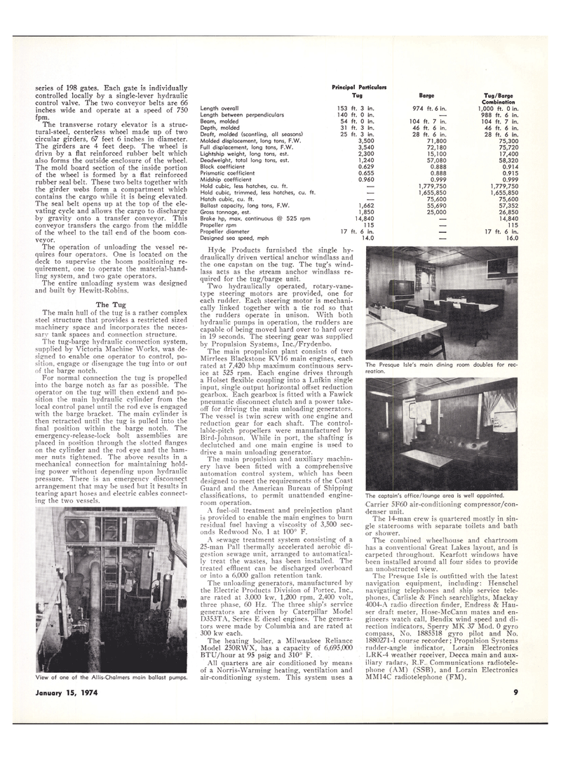
View of one of the Allis-Chalmers main ballast pumps.
January 15, 1974 9
Length overall
Length between perpendiculars
Beam, molded
Depth, molded
Draft, molded (scantling, all seasons)
Molded displacement, long tons, F.W.
Full displacement, long tons, F.W.
Lightship weight, long tons, est.
Deadweight, total long tons, est.
Block coefficient
Prismatic coefficient
Midship coefficient
Hold cubic, less hatches, cu. ft.
Hold cubic, trimmed, less hatches, cu. ft.
Hatch cubic, cu. ft.
Ballast capacity, long tons, F.W.
Gross tonnage, est.
Brake hp, max. continuous @ 525 rpm
Propeller rpm
Propeller diameter
Designed sea speed, mph
Hyde Products furnished the single hy- draulically driven vertical anchor windlass and the one capstan on the tug. The tug's wind- lass acts as the stream anchor windlass re- quired for the tug/barge unit.
Two hydraulically operated, rotary-vane- type steering motors are provided, one for each rudder. Each steering motor is mechani- cally linked together with a tie rod so that the rudders operate in unison. With both hydraulic pumps in operation, the rudders are capable of being moved hard over to hard over in 19 seconds. The steering gear was supplied by Propulsion Systems, Inc./Frydenbo.
The main propulsion plant consists of two
Mirrlees Blackstone KVi6 main engines, each rated at 7,420 bhp maximum continuous serv- ice at 525 rpm. Each engine drives through a Holset flexible coupling into a Lufkin single input, single output horizontal offset reduction gearbox. Each gearbox is fitted with a Fawick pneumatic disconnect clutch and a power take- off for driving the main unloading generators.
The vessel is twin screw with one engine and reduction gear for each shaft. The control- lable-pitch propellers were manufactured by
Bird-Johnson. While in port, the shafting is declutched and one main engine is used to drive a main unloading generator.
The main propulsion and auxiliary machin- ery have been fitted with a comprehensive automation control system, which has been designed to meet the requirements of the Coast
Guard and the American Bureau of Shipping classifications, to permit unattended engine- room operation.
A fuel-oil treatment and preinjection plant is provided to enable the main engines to burn residual fuel having a viscosity of 3,500 sec- onds Redwood No.' 1 at 100° F.
A sewage treatment system consisting of a 25-man Pall thermally accelerated aerobic di- gestion sewage unit, arranged to automatical- ly treat the wastes, has been installed. The treated effluent can be discharged overboard or into a 6,000 gallon retention tank.
The unloading generators, manufactured by the Electric Products Division of Portec, Inc., are rated at 3.000 kw. 1,200 rpm, 2,400 volt, three phase, 60 Hz. The three ship's service generators are driven by Caterpillar Model
D353TA, Series E diesel engines. The genera- tors were made by Columbia and are rated at 300 kw each.
The heating boiler, a Milwaukee Reliance
Model 250RWX, has a capacity of 6,695,000
BTU/hour at 95 psig and 310° F.
All quarters are air conditioned by means of a Norris-Warming heating, ventilation and air-conditioning system. This system uses a 3 in. 0 in.
Barge 974 ft. 6 in. 54 ft. 0 in. in. in. 104 46 28 3,500 3,540 2,300 1,240 0.629 0.655 0.960 ft. 7 in. ft. 6 in. ft. 6 in. 71,800 72,180 15,100 57,080 0.888 0.888 0.999 1,779,750 1,655,850 75,600 55,690 25,000
Tug/Barge
Combination 1,000 ft. Oin. 988 ft. 6 in. 104 ft. 7 in. 46 ft. 6 in. 28 ft. 6 in.
The Presque Isle's main dining room doubles for rec- reation.
The captain's office/lounge area is well appointed.
Carrier 5F60 air-conditioning compressor/con- denser unit.
The 14-man crew is quartered mostly in sin- gle staterooms with separate toilets and bath or shower.
The combined wheelhouse and chartroom has a conventional Great Lakes layout, and is carpeted throughout. Kearfott windows have been installed around all four sides to provide an unobstructed view.
The Presque Isle is outfitted with the latest navigation equipment, including: Henschel navigating telephones and ship service tele- phones, Carlisle & Finch searchlights, Mackay 4004-A radio direction finder, Endress & Hau- ser draft meter, Hose-McCann mates and en- gineers watch call, Bendix wind speed and di- rection indicators, Sperry MK 37 Mod. 0 gyro compass, No. 1885518 gyro pilot and No. 1880271-1 course recorder; Propulsion Systems rudder-angle indicator, Lorain Electronics
LRK-4 weather receiver, Decca main and aux- iliary radars, R.F. Communications radiotele- phone (AM) (SS'B), and Lorain Electronics
MM14C radiotelephone (FM).
