
Page 28: of Maritime Reporter Magazine (August 1996)
Read this page in Pdf, Flash or Html5 edition of August 1996 Maritime Reporter Magazine
 27
27
 29
29
mi
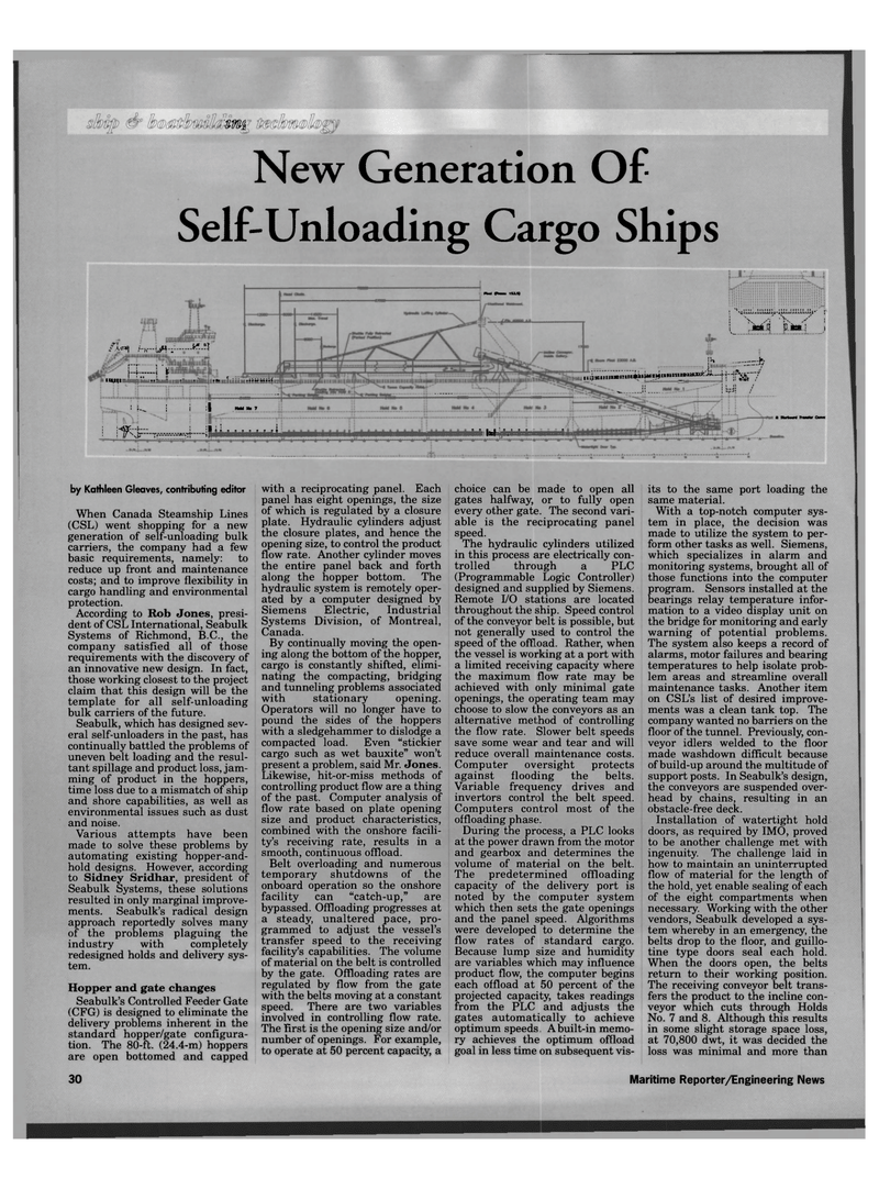
New Generation Of
Self-Unloading Cargo Ships /La, K-n j4=—I ¥ MWftMMHhli iiMMK^uiuluiKBiluuiH
CM (Tram* 1S15) tEflBasiiiiiKiiiHHilii 3IWC .... I I 1 i | i :§ ho« no 7
I j ji i i M 111 i j ^»4iLLIjjiLUJJi).-iLlJaJiiLLLjJii' ; •- i .-;' -V ,--'* :
L ; p to" } J
I'r, it J—1 as^-'iil U—JiV-r ~f iis^V^ 7 i! }WI /
III Ijjl I * i i • MM4 Tnmfr Con* by Kathleen Gleaves, contributing editor
When Canada Steamship Lines (CSL) went shopping for a new generation of self-unloading bulk carriers, the company had a few basic requirements, namely: to reduce up front and maintenance costs; and to improve flexibility in cargo handling and environmental protection.
According to Rob Jones, presi- dent of CSL International, Seabulk
Systems of Richmond, B.C., the company satisfied all of those requirements with the discovery of an innovative new design. In fact, those working closest to the project claim that this design will be the template for all self-unloading bulk carriers of the future.
Seabulk, which has designed sev- eral self-unloaders in the past, has continually battled the problems of uneven belt loading and the resul- tant spillage and product loss, jam- ming of product in the hoppers, time loss due to a mismatch of ship and shore capabilities, as well as environmental issues such as dust and noise.
Various attempts have been made to solve these problems by automating existing hopper-and- hold designs. However, according to Sidney Sridhar, president of
Seabulk Systems, these solutions resulted in only marginal improve- ments. Seabulk's radical design approach reportedly solves many of the problems plaguing the industry with completely redesigned holds and delivery sys- tem.
Hopper and gate changes
Seabulk's Controlled Feeder Gate (CFG) is designed to eliminate the delivery problems inherent in the standard hopper/gate configura- tion. The 80-ft. (24.4-m) hoppers are open bottomed and capped with a reciprocating panel. Each panel has eight openings, the size of which is regulated by a closure plate. Hydraulic cylinders adjust the closure plates, and hence the opening size, to control the product flow rate. Another cylinder moves the entire panel back and forth along the hopper bottom. The hydraulic system is remotely oper- ated by a computer designed by
Siemens Electric, Industrial
Systems Division, of Montreal,
Canada.
By continually moving the open- ing along the bottom of the hopper, cargo is constantly shifted, elimi- nating the compacting, bridging and tunneling problems associated with stationary opening.
Operators will no longer have to pound the sides of the hoppers with a sledgehammer to dislodge a compacted load. Even "stickier cargo such as wet bauxite" won't present a problem, said Mr. Jones.
Likewise, hit-or-miss methods of controlling product flow are a thing of the past. Computer analysis of flow rate based on plate opening size and product characteristics, combined with the onshore facili- ty's receiving rate, results in a smooth, continuous offload.
Belt overloading and numerous temporary shutdowns of the onboard operation so the onshore facility can "catch-up," are bypassed. Offloading progresses at a steady, unaltered pace, pro- grammed to adjust the vessel's transfer speed to the receiving facility's capabilities. The volume of material on the belt is controlled by the gate. Offloading rates are regulated by flow from the gate with the belts moving at a constant speed. There are two variables involved in controlling flow rate.
The first is the opening size and/or number of openings. For example, to operate at 50 percent capacity, a choice can be made to open all gates halfway, or to fully open every other gate. The second vari- able is the reciprocating panel speed.
The hydraulic cylinders utilized in this process are electrically con- trolled through a PLC (Programmable Logic Controller) designed and supplied by Siemens.
Remote I/O stations are located throughout the ship. Speed control of the conveyor belt is possible, but not generally used to control the speed of the offl oad. Rather, when the vessel is working at a port with a limited receiving capacity where the maximum flow rate may be achieved with only minimal gate openings, the operating team may choose to slow the conveyors as an alternative method of controlling the flow rate. Slower belt speeds save some wear and tear and will reduce overall maintenance costs.
Computer oversight protects against flooding the belts.
Variable frequency drives and invertors control the belt speed.
Computers control most of the offloading phase.
During the process, a PLC looks at the power drawn from the motor and gearbox and determines the volume of material on the belt.
The predetermined offloading capacity of the delivery port is noted by the computer system which then sets the gate openings and the panel speed. Algorithms were developed to determine the flow rates of standard cargo.
Because lump size and humidity are variables which may influence product flow, the computer begins each offload at 50 percent of the projected capacity, takes readings from the PLC and adjusts the gates automatically to achieve optimum speeds. A built-in memo- ry achieves the optimum offload goal in less time on subsequent vis- its to the same port loading the same material.
With a top-notch computer sys- tem in place, the decision was made to utilize the system to per- form other tasks as well. Siemens, which specializes in alarm and monitoring systems, brought all of those functions into the computer program. Sensors installed at the bearings relay temperature infor- mation to a video display unit on the bridge for monitoring and early warning of potential problems.
The system also keeps a record of alarms, motor failures and bearing temperatures to help isolate prob- lem areas and streamline overall maintenance tasks. Another item on CSL's list of desired improve- ments was a clean tank top. The company wanted no barriers on the floor of the tunnel. Previously, con- veyor idlers welded to the floor made washdown difficult because of build-up around the multitude of support posts. In Seabulk's design, the conveyors are suspended over- head by chains, resulting in an obstacle-free deck.
Installation of watertight hold doors, as required by IMO, proved to be another challenge met with ingenuity. The challenge laid in how to maintain an uninterrupted flow of material for the length of the hold, yet enable sealing of each of the eight compartments when necessary. Working with the other vendors, Seabulk developed a sys- tem whereby in an emergency, the belts drop to the floor, and guillo- tine type doors seal each hold.
When the doors open, the belts return to their working position.
The receiving conveyor belt trans- fers the product to the incline con- veyor which cuts through Holds
No. 7 and 8. Although this results in some slight storage space loss, at 70,800 dwt, it was decided the loss was minimal and more than 30 Maritime Reporter/Engineering News
