Page 70: of Maritime Reporter Magazine (September 1997)
Read this page in Pdf, Flash or Html5 edition of September 1997 Maritime Reporter Magazine
MARINE PROPULSION TECHNOLOGY — RESEARCH AND DEVELOPMENT
ERAM
A Revolutionary, International Approach To Engine Room Design
This is the first article in a four-part series describing a project executed by the U.S. Navy in partnership with domestic and inter- national designers from shipyards, shipowner!operators and marine equipment vendors. The project involved an Engine Room
Arrangement Model (ERAM) study. One medium-speed diesel (MSD) and three low-speed diesel (SSD) engine rooms were designed in the course of two years. Each MR/EN article will focus on one of the four engine room design products; the evolution of applying the
IPPD methodology process; and the lessons learned from each stage of the project. Noteworthy product improvements realized dur- ing each stage will be highlighted.
With the end of the Cold War, the
U.S. Navy was directed to pursue militarily useful and commercially viable ships for sealift.
In November 1993, the
Shipbuilding Technology
Department of the David Taylor
Model Basin (DTMB) was tasked by the Mid-Term Strategic Sealift
Technology Development Program (MTSSTDP) with conducting research to improve the efficiency of ships by focusing on the engine room — which accounts for 40 to 45 percent of the initial acquisition cost.
The Producibility Task goals were to develop product (ship) designs that could be built with a construction schedule reduction of 40 percent (down to 18 months) and acquisition cost reduction of 15 percent (down to $25 million for the engine room). To meet these aggressive goals, the ERAM pro- ject was initiated.
ERAM: Efficiency & Cost
Effectiveness By Design
The initial efforts involved the baselining of world class (-30,000 shp) ships as well as their con- struction yard processes. Also, a shipbuilding industry/MTSSTDP workshop was conducted where the overall goals of the project were defined using Quality
Function Deployment (QFD).
These goals were compiled in the
ERAM Requirements Document, which would be the guidance docu- ment for the project.
A design site was set up at
DTMB for 20 engineers and designers, using Intergraph work- stations for the 3-D product model- ing effort. In addition, a library of vendor-furnished information was assembled, based on lists of likely equipment types utilized in typical 30,000 shp plants. A steering com- mittee was formed, comprised of representatives from U.S. ship- yards, Navy sponsors, a design agent, ship owner/operators and a university. The Steering
Committee theorized that since the U.S. shipyards had not built commercially competitive ships in more than a decade, an Integrated
Product Team (IPT) should be assembled consisting of both for- eign and domestic designers from shipyards, ship operators and marine equipment vendors.
When the ERAM Team was assembled at the DTMB design site in June 1995, all core and resource members were trained in, customized and executed
Concurrent Engineering (CE) tech- niques including: Integrated
Product & Process Development (IPPD); QFD; Strategic Design
Method (SDM); as well as teaming basics.
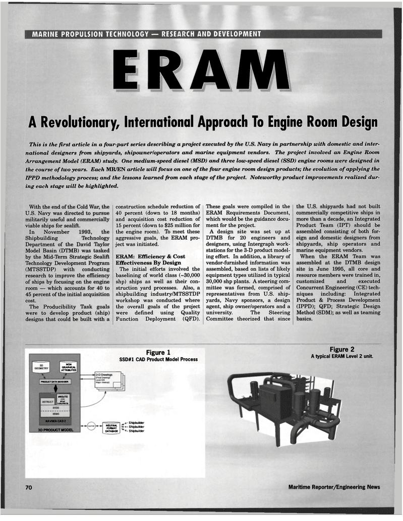
NON
GRAPHICAL
ATTRIBUTES
PRODUCT DATA MANAGER
I l/ROUTE
BVAC CABLE WAYS)
NAVSEA CAD 2 3D PRODUCT MODEL
Figure 1
SSD#1 CAD Product Model Process
NEUTRAL
FORMAT
DATABASE ' Shipbuilder . Shipbuilder • Shipbuilder
Figure 2
A typical ERAM Level 2 unit. 70 Maritime Reporter/Engineering News

 69
69

 71
71
