
Page 22: of Maritime Reporter Magazine (April 2016)
The Offshore Annual
Read this page in Pdf, Flash or Html5 edition of April 2016 Maritime Reporter Magazine
 21
21
 23
23
PROPULSION
Figure 1 Figure 2 Figure 3 Figure 4
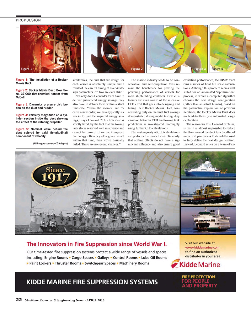
Figure 1: The installation of a Becker similarities, the duct that we design for The marine industry tends to be con- cavitation performance, the IBMV team
Mewis Duct.
each vessel is absolutely unique and a servative, and self-propulsion tests re- runs a series of ? nal full scale calcula- result of the careful tuning of over 40 de- main the benchmark for proving the tions. Although this problem seems well
Figure 2: Becker Mewis Duct, Bow Flo- sign parameters. No two are ever alike.” powering performance of vessels for suited for an automated “optimization” ra, 37,000 dwt chemical tanker from
Not only does Leonard’s team have to most shipbuilding contracts. Few cus- process, in which a computer algorithm
Odfjell.
deliver guaranteed energy savings they tomers are even aware of the intensive chooses the next design con? guration also have to deliver them within a strict CFD effort that goes into designing and (rather than an actual human), based on
Figure 3: Dynamics pressure distribu- tion on the duct and rudder.
timescale. “From the moment we re- tuning their Becker Mewis Duct, con- the parametric exploration of previous ceive a new order, we have typically six centrating only on the ? nal fuel savings iterations, the Becker Mewis Duct does
Figure 4: Vorticity magnitude on a cyl- weeks to ? nd the required energy sav- demonstrated during model testing. Any not lend itself easily to automated design inder section inside the duct showing ings,” says Leonard. “This timescale is variation between CFD and towing tank exploration. the effect of the rotating propeller.
strictly ? xed, by the fact that the towing predictions is investigated thoroughly The reason for this, Leonard explains, tank slot is reserved well in advance and using further CFD calculations. is that it is almost impossible to reduce
Figure 5: Nominal wake behind the cannot be moved. If we can’t improve The vast majority of CFD calculations the ? ow around the duct to a handful of duct colored by axial (longitudinal) component of velocity.
the energy ef? ciency of a given vessel are performed at model scale. To verify numerical parameters that could be used within that time, then we’ve basically that scaling effects do not have a sig- to fully de? ne the next design iteration. (All images courtesy CD Adapco) failed. There are no second chances.” ni? cant in? uence and also ensure good Instead, Leonard relies on a team of ex- 22 Maritime Reporter & Engineering News • APRIL 2016
MR #4 (18-25).indd 22 4/6/2016 5:29:51 PM
