Page 22: of Maritime Reporter Magazine (October 2016)
Marine Design Annual
Read this page in Pdf, Flash or Html5 edition of October 2016 Maritime Reporter Magazine
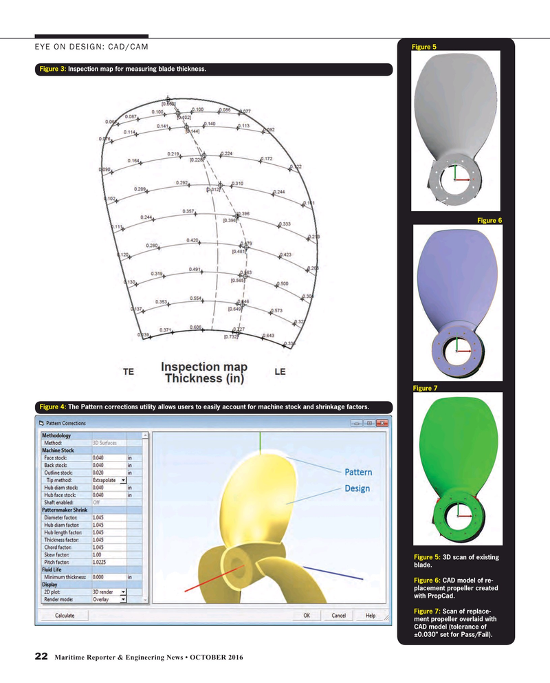
Figure 5
EYE ON DESIGN: CAD/CAM
Figure 3: Inspection map for measuring blade thickness.
Figure 6
Figure 7
Figure 4: The Pattern corrections utility allows users to easily account for machine stock and shrinkage factors.
Figure 5: 3D scan of existing blade.
Figure 6: CAD model of re- placement propeller created with PropCad.
Figure 7: Scan of replace- ment propeller overlaid with
CAD model (tolerance of ±0.030” set for Pass/Fail).
22 Maritime Reporter & Engineering News • OCTOBER 2016
MR #10 (18-25).indd 22 10/3/2016 3:27:08 PM

 21
21

 23
23
