
Page 67: of Offshore Engineer Magazine (Aug/Sep 2014)
Read this page in Pdf, Flash or Html5 edition of Aug/Sep 2014 Offshore Engineer Magazine
 66
66
 68
68
makes defning a safety factor the key was also set when the biggest slings
Fig. 1 ENI’s Goliat FPSO.
EPIC
Image from ENI Norge. challenge. were 140mm in diameter—now they are
Wire and fber slings are used for 400mm. next year. The simulations, lifting and can undergo great dynamic “The failure mode of spliced cable carried out in three phases loads. Depending on the material, the laid sling is not fully understood,”
Breedeveld says. “An IMCA sub-group during design, uncovered break load is calculated in different of the crane and winch operations blind zones and challeng- ways. In steel rope slings, the break load workgroup is working on an update of ing lift scenarios that were in individual wires is measured and then able to be changed or then the total rope break load calculated.
IMCA M179 and hopefully by the end mitigated. But there are limited available test facili- of the year there will be an updated
Torbjorn Alstad, SMSC’s standard,” he adds. But more tests are ties, in terms of capacity and length, chief marketing offcer, needed to better defne the design fac- to test complete steel cable laid slings. told the conference that tors in such cable and cutting of core
Guidance for spliced cable laid slings using the actual design models, SMSC devel- oped simulator models and performed simulated operations for Goliat’s two cranes. This meant blind zones, where the crane operator would not be able to see, lifting corridors, and exhaust zones could be modeled and assessed and changes made to the design before construction started. Certain areas were strengthened, due to being in potential risk of being knocked.
Also, which crane corridors would be best utilized for specifc tasks were identifed.
From simulation to WRR
The changes also meant improve- ments in the overall design, because it identifed extra lay-down area. Where hen it comes to offshore changes could not be made to mitigate lifting, it is usually the an identifed problem, alternatives
W heavy installation vessels were suggested and adopted, such and barges that get most of the attention. as focusing on the communication
But, there is much more to offshore between the crane operator and deck lifting operations, from lift modeling, personnel. “The projects have uncovered blind and crane design and fabrication, to rope zones and challenging lifts at a very manufacture and certifcation, and rope early stage, enabling us to make neces- lubrication and testing. These factors sary changes. It was the frst time we stretch right through project life-cycles had done something like this and I and the supply chain, from rope and believe more companies should do this crane manufacture to design integration type of thing, it would save them a lot and operations. of money,” Alstad says.
Norway’s Ship Modelling &
Simulation Centre (SMSC) demonstrated
Slings how knowing how a rope or crane will perform will be benefcial during front Computer modeling could potentially be end engineering and design, at the used to calculate break loads, suggests
North Sea Offshore Crane and Lifting Jan-Peter Breedeveld, engineering direc-
Conference, held in Aberdeen in late tor, Seaway Heavy Lifting, Netherlands.
April. He suggests that few know the actual break load and failure modes in large
Simulation diameter cable laid slings, which
SMSC used a crane simulator to
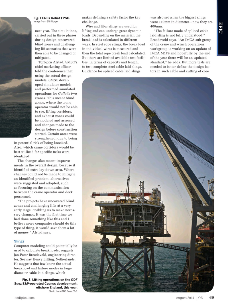
Fig. 3 Lifting operations on the GDF improve the crane integration on ENI’s
Suez E&P-operated Cygnus development,
Goliat FPSO, which is due to start pro- ofshore England, this year. duction in the Norwegian Barents Sea
Photo from GDF Suez E&P.
oedigital.com August 2014 | OE 69 000_OE0814_EPIC4_OffshoreLift.indd 69 7/22/14 10:20 PM