
Page 28: of Marine Technology Magazine (May 2008)
Undersea Defense Edition
Read this page in Pdf, Flash or Html5 edition of May 2008 Marine Technology Magazine
 27
27
 29
29
three dimensions. The inner-workings of an INS can seem a bit "blackbox". However, if we think back to our col- lege-level physics, an instantaneous measured acceleration can be integrated with respect to time to generate a veloc- ity. Removing the calculus notation, the equation is: v t = v 0 + (a t . t)
This is read as: the velocity at any time t is equal to a starting velocity plus change in velocity due to an acceler- ation applied over an incremental change in time t. A sec- ond integration can generate a displacement. x t = x 0 + (v t . t) such that the location x at time t is equal to a starting location plus a change in location due to the velocity over an incremental change in time t.
Unfortunately, a stand-alone INS has a tendency to drift because it does not sense constant velocity drift. Without aiding from an external source, an INS can only generate its own values for the constant velocity (the v0 member of the equation above). The INS struggles to accommodate three-dimensional longterm drift, so Kearfott aides the
INS in the MiniPos by providing it with a Teledyne-RD
Instruments Doppler Velocity Log (DVL) and, in this case, a DigiQuartz pressure/depth sensor. The DVL pro- vides real-time constant velocity measurements that aid the INS to account for horizontal (xy) drift. The
DigiQuartz pressure sensor, accurate to nearly 0.01% of actual depth, provides a vertical correction to aid the INS.
These inputs, combined with the dead-reckoning solution from the RLG and linear accelerometers, are fed through onboard hardware and firmware that run a series of
Kalman filtering algorithms that generate the aided iner- tial navigation solution.
The pairing (the INS and the DVL) mounted to an
ROV instrument skid are run through a "training" or cal- ibration routine prior to the actual survey so that the
Kalman filters can be taught how to combine the infor- mation from the INS and the DVL to generate a highly accurate positioning solution. For this project, SeaVision teamed with Nuytco to accept delivery of the instrumen- tation at Nuytco's offices in Vancouver, install the
MiniPOS INS and the Teledyne-RDI DVL to the tooling skid, and perform the training calibration routines from a survey vessel near Port Coquitlam, British Columbia.
After calibration, the result was an instrument skid that was ready to be mounted to the underside of the ROV (in our case, the SeaEye Falcon), powered from the ROV, and capable of outputting a single data stream that contains the x,y,z positioning, the heading, pitch, and roll and the velocity of the ROV in real-time at an update rate of 28 MTR May 2008
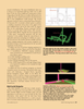
A view from the perspective of the Falcon, from within the Shaft 1 chamber alongside the elevator that carried the deployment garage to the 480-meter level.
SeaVision color-coded the different spurs off of the pri- mary drift so that the SeaView's ROV operator knew which tunnel was the target. The spur tunnels do not actually come into the interior of the main drift; rather, that is an artifact of the 3DTV shapes used to develop the concept model for the project.
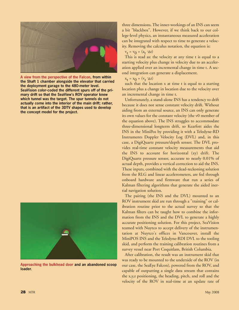
Approaching the bulkhead door and an abandoned scoop loader.
MTR#4 (17-32).qxd 5/13/2008 10:00 AM Page 28