Page 59: of Marine Technology Magazine (September 2014)
Ocean Observation: Gliders, Buoys & Sub-Surface Networks
Read this page in Pdf, Flash or Html5 edition of September 2014 Marine Technology Magazine
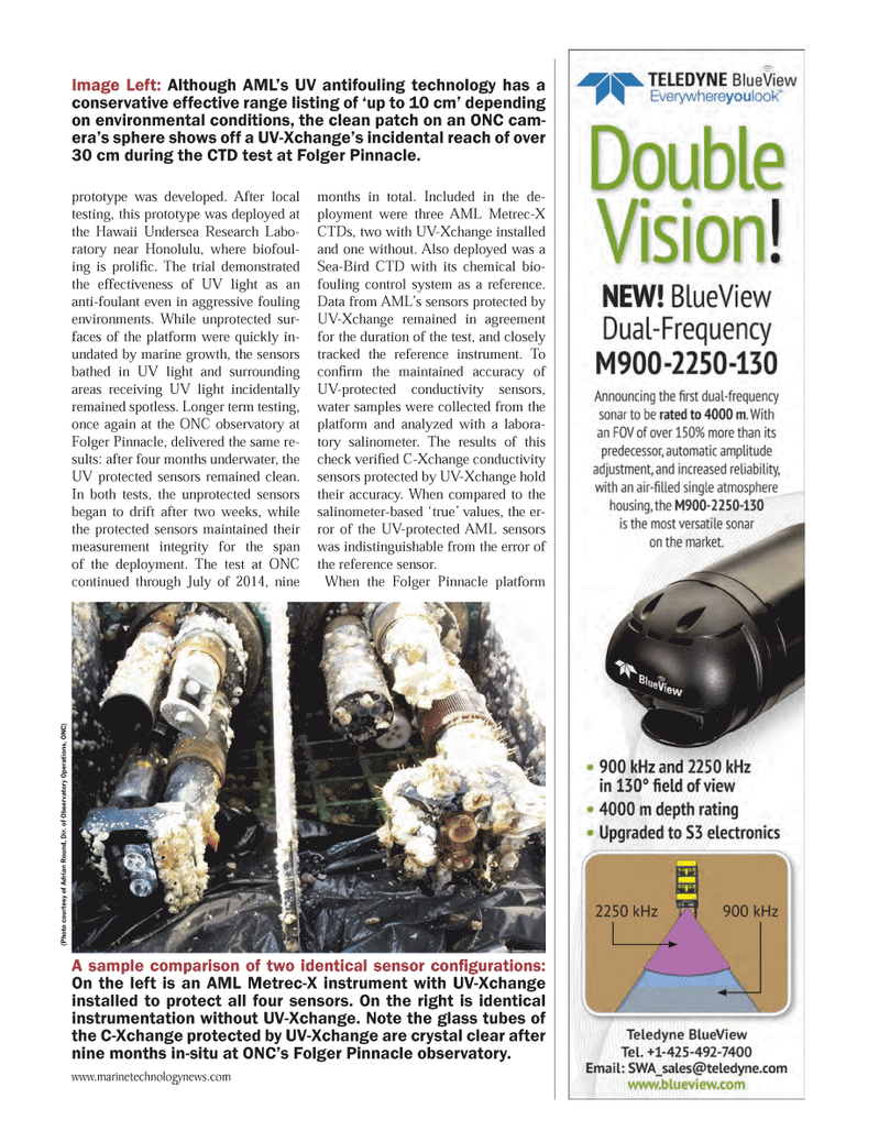
prototype was developed. After local testing, this prototype was deployed at the Hawaii Undersea Research Labo- ratory near Honolulu, where biofoul- ing is prolifi c. The trial demonstrated the effectiveness of UV light as an anti-foulant even in aggressive fouling environments. While unprotected sur- faces of the platform were quickly in- undated by marine growth, the sensors bathed in UV light and surrounding areas receiving UV light incidentally remained spotless. Longer term testing, once again at the ONC observatory at
Folger Pinnacle, delivered the same re- sults: after four months underwater, the
UV protected sensors remained clean.
In both tests, the unprotected sensors began to drift after two weeks, while the protected sensors maintained their measurement integrity for the span of the deployment. The test at ONC continued through July of 2014, nine months in total. Included in the de- ployment were three AML Metrec-X
CTDs, two with UV-Xchange installed and one without. Also deployed was a
Sea-Bird CTD with its chemical bio- fouling control system as a reference.
Data from AML’s sensors protected by
UV-Xchange remained in agreement for the duration of the test, and closely tracked the reference instrument. To confi rm the maintained accuracy of
UV-protected conductivity sensors, water samples were collected from the platform and analyzed with a labora- tory salinometer. The results of this check verifi ed C-Xchange conductivity sensors protected by UV-Xchange hold their accuracy. When compared to the salinometer-based ‘true’ values, the er- ror of the UV-protected AML sensors was indistinguishable from the error of the reference sensor.
When the Folger Pinnacle platform
Image Left: Although AML’s UV antifouling technology has a conservative effective range listing of ‘up to 10 cm’ depending on environmental conditions, the clean patch on an ONC cam- era’s sphere shows off a UV-Xchange’s incidental reach of over 30 cm during the CTD test at Folger Pinnacle.
A sample comparison of two identical sensor confi gurations:
On the left is an AML Metrec-X instrument with UV-Xchange installed to protect all four sensors. On the right is identical instrumentation without UV-Xchange. Note the glass tubes of the C-Xchange protected by UV-Xchange are crystal clear after nine months in-situ at ONC’s Folger Pinnacle observatory. (Photo cour tesy of Adrian R ound, Dir . of Obser v ator y Operations, ONC) www.marinetechnologynews.com
MTR #7 (50-65).indd 59 8/27/2014 11:06:33 AM

 58
58

 60
60
