
Page 16: of Marine Technology Magazine (January 2016)
Underwater Vehicle Annual: ROV, AUV, and UUVs
Read this page in Pdf, Flash or Html5 edition of January 2016 Marine Technology Magazine
 15
15
 17
17
Fiber Insights
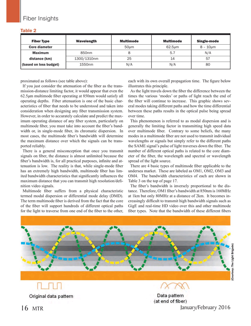
Table 2 Fiber Type Wavelength Multimode Multimode Single-mode Core diameter 50µm 62.5µm 8 – 10µm Maximum 850nm 8 5.7 N/A distance (km) 1300/1310nm 25 14 57 (based on loss budget) 1550nm N/A N/A 80 proximated as follows (see table above): each with its own overall propagation time. The ? gure below
If you just consider the attenuation of the ? ber as the trans- illustrates this principle. mission-distance limiting factor, it would appear that even the As the light travels down the ? ber the difference between the 62.5µm multimode ? ber operating at 850nm would satisfy all times the various ‘modes’ or paths of light reach the end of operating depths. Fiber attenuation is one of the basic char- the ? ber will continue to increase. This graphic shows sev- acteristics of ? ber that needs to be understood and taken into eral modes taking different paths and how the time differential consideration when designing any ? ber transmission system. between these paths results in the optical pulse being spread
However, in order to accurately calculate and predict the max- over time. imum operating distance of any ? ber system, particularly on This phenomenon is referred to as modal dispersion and is multimode ? ber, you must take into account the ? ber’s band- generally the limiting factor in transmitting high speed data width or, in single-mode ? ber, its chromatic dispersion. In over multimode ? ber. Contrary to some beliefs, the many most cases, the multimode ? ber’s bandwidth will determine modes in a multimode ? ber are not used to transmit individual the maximum distance over which the signals can be trans- wavelengths or signals but simply refer to the different paths ported reliably. the SAME signal’s pulse of light traverses down the ? ber. The
There is a general misconception that once you transmit number of different optical paths is related to the core diam- signals on ? ber, the distance is almost unlimited because the eter of the ? ber, the wavelength and spectral or wavelength ? ber’s bandwidth is, for all practical purposes, in? nite and at- spread of the light source. tenuation is low. The reality is that, while single-mode ? ber There are 4 basic types of multimode ? ber applicable to the has an extremely high bandwidth, multimode ? ber has lim- undersea market. These are labeled as OM1, OM2, OM3 and ited bandwidth characteristics that signi? cantly in? uences the OM4. The bandwidth characteristics of each are shown in maximum distance that you can transmit high resolution/de? - Table 3 on the top of page 17.
nition video signals. The ? ber’s bandwidth is inversely proportional to the dis-
Multimode ? ber suffers from a physical characteristic tance. Therefore, OM1 ? ber’s bandwidth at 850nm is 160MHz termed modal dispersion or differential mode delay (DMD). at 1km but only 80MHz at a distance of 2km. It becomes in-
The term multimode ? ber is derived from the fact that the core creasingly dif? cult to transmit high bandwidth signals such as of the ? ber will support hundreds of different optical paths GigE and real-time HD video over this and other multimode for the light to traverse from one end of the ? ber to the other, ? ber types. Note that the bandwidth of these different ? bers (Courtesy: The Light Brigade)
January/February 2016 16
MTR
MTR #1 (1-17).indd 16 1/26/2016 11:59:09 AM