
Page 22: of Marine Technology Magazine (March 2016)
Oceanographic Instrumentation: Measurement, Process & Analysis
Read this page in Pdf, Flash or Html5 edition of March 2016 Marine Technology Magazine
 21
21
 23
23
Fiber Insights
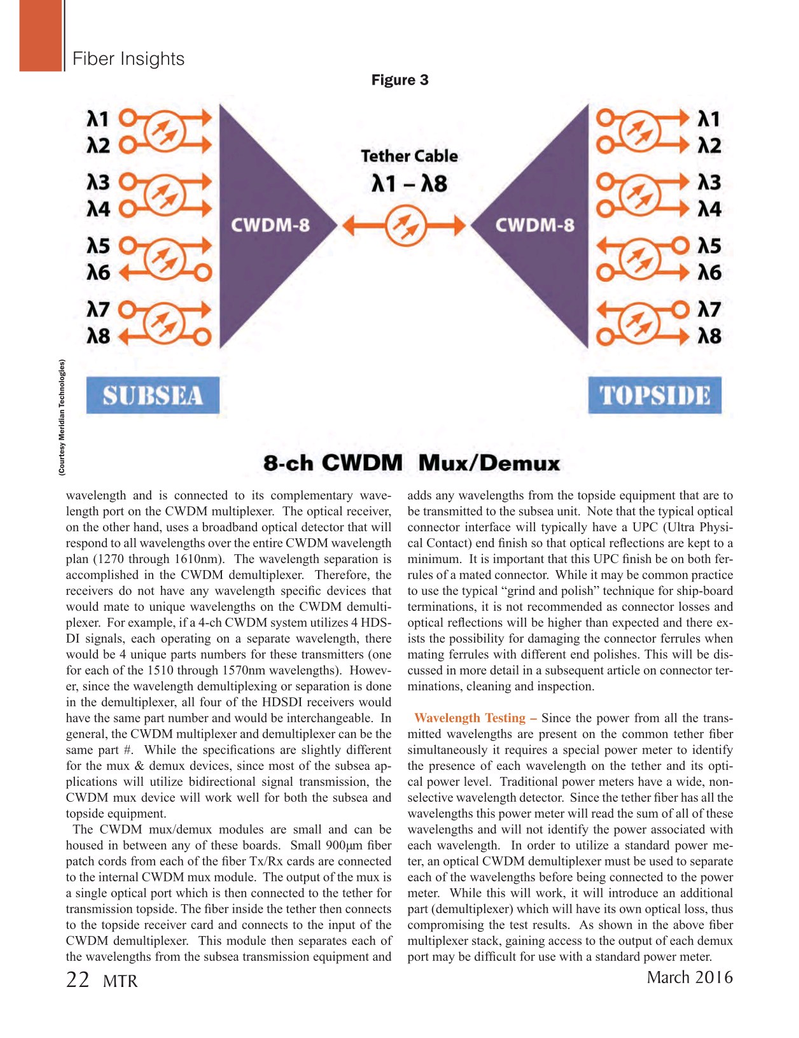
Figure 3 (Courtesy Meridian Technologies) wavelength and is connected to its complementary wave- adds any wavelengths from the topside equipment that are to length port on the CWDM multiplexer. The optical receiver, be transmitted to the subsea unit. Note that the typical optical on the other hand, uses a broadband optical detector that will connector interface will typically have a UPC (Ultra Physi- respond to all wavelengths over the entire CWDM wavelength cal Contact) end ? nish so that optical re? ections are kept to a plan (1270 through 1610nm). The wavelength separation is minimum. It is important that this UPC ? nish be on both fer- accomplished in the CWDM demultiplexer. Therefore, the rules of a mated connector. While it may be common practice receivers do not have any wavelength speci? c devices that to use the typical “grind and polish” technique for ship-board would mate to unique wavelengths on the CWDM demulti- terminations, it is not recommended as connector losses and plexer. For example, if a 4-ch CWDM system utilizes 4 HDS- optical re? ections will be higher than expected and there ex-
DI signals, each operating on a separate wavelength, there ists the possibility for damaging the connector ferrules when would be 4 unique parts numbers for these transmitters (one mating ferrules with different end polishes. This will be dis- for each of the 1510 through 1570nm wavelengths). Howev- cussed in more detail in a subsequent article on connector ter- er, since the wavelength demultiplexing or separation is done minations, cleaning and inspection.
in the demultiplexer, all four of the HDSDI receivers would have the same part number and would be interchangeable. In Wavelength Testing – Since the power from all the trans- general, the CWDM multiplexer and demultiplexer can be the mitted wavelengths are present on the common tether ? ber same part #. While the speci? cations are slightly different simultaneously it requires a special power meter to identify for the mux & demux devices, since most of the subsea ap- the presence of each wavelength on the tether and its opti- plications will utilize bidirectional signal transmission, the cal power level. Traditional power meters have a wide, non-
CWDM mux device will work well for both the subsea and selective wavelength detector. Since the tether ? ber has all the topside equipment. wavelengths this power meter will read the sum of all of these
The CWDM mux/demux modules are small and can be wavelengths and will not identify the power associated with housed in between any of these boards. Small 900µm ? ber each wavelength. In order to utilize a standard power me- patch cords from each of the ? ber Tx/Rx cards are connected ter, an optical CWDM demultiplexer must be used to separate to the internal CWDM mux module. The output of the mux is each of the wavelengths before being connected to the power a single optical port which is then connected to the tether for meter. While this will work, it will introduce an additional transmission topside. The ? ber inside the tether then connects part (demultiplexer) which will have its own optical loss, thus to the topside receiver card and connects to the input of the compromising the test results. As shown in the above ? ber
CWDM demultiplexer. This module then separates each of multiplexer stack, gaining access to the output of each demux the wavelengths from the subsea transmission equipment and port may be dif? cult for use with a standard power meter.
March 2016 22
MTR
MTR #2 (18-33).indd 22 2/19/2016 11:02:16 AM