
Page 48: of Marine Technology Magazine (September 2019)
Autonomous Vehicle Operations
Read this page in Pdf, Flash or Html5 edition of September 2019 Marine Technology Magazine
 47
47
 49
49
Tech Files Thrusters
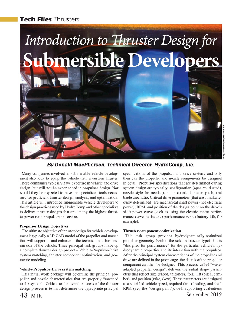
Introduction to T ruster Design for
Submersible Developers
Images Courtesy Hydrocomp Inc.
By Donald MacPherson, Technical Director, HydroComp, Inc.
Many companies involved in submersible vehicle develop- speci? cations of the propulsor and drive system, and only ment also look to equip the vehicle with a custom thruster. then can the propeller and nozzle components be designed
These companies typically have expertise in vehicle and drive in detail. Propulsor speci? cations that are determined during design, but will not be experienced in propulsor design. Nor system design are typically: con? guration (open vs. ducted), would they be expected to have the specialized tools neces- nozzle style (as needed), blade count, diameter, pitch, and sary for pro? cient thruster design, analysis, and optimization. blade area ratio. Critical drive parameters (that are simultane-
This article will introduce submersible vehicle developers to ously determined) are mechanical shaft power (not electrical the design practices used by HydroComp and other specialists power), RPM, and position of the design point on the drive’s to deliver thruster designs that are among the highest thrust- shaft power curve (such as using the electric motor perfor- to-power ratio propulsors in service. mance curves to balance performance versus battery life, for example).
Propulsor Design Objectives
The ultimate objective of thruster design for vehicle develop- Thruster component optimization ment is typically a 3D CAD model of the propeller and nozzle This task group provides hydrodynamically-optimized that will support – and enhance – the technical and business propeller geometry (within the selected nozzle type) that is mission of the vehicle. Three principal task groups make up “designed for performance” for the particular vehicle’s hy- a complete thruster design project – Vehicle-Propulsor-Drive drodynamic properties and its interaction with the propulsor. system matching, thruster component optimization, and geo- After the principal system characteristics of the propeller and metric modeling. drive are de? ned in the prior stage, the details of the propeller component can then be designed. This process, called “wake-
Vehicle-Propulsor-Drive system matching adapted propeller design”, delivers the radial shape param-
This initial work package will determine the principal pro- eters that re? ect size (chord, thickness, foil), lift (pitch, cam- peller and nozzle characteristics that are properly “matched ber), and position (rake, skew). These parameters are designed to the system”. Critical to the overall success of the thruster to a speci? ed vehicle speed, required thrust loading, and shaft design process is to ? rst determine the appropriate principal RPM (i.e., the “design point”), with supporting evaluations
September 2019
MTR 48
MTR #7 (34-49).indd 48 9/4/2019 9:36:15 AM