
Page 10: of Marine Technology Magazine (July 2021)
Autonomous Vehicle Operations
Read this page in Pdf, Flash or Html5 edition of July 2021 Marine Technology Magazine
 9
9
 11
11
Thruster Tech Underwater Propulsion ciency are that a) motor suppliers gen- performance coef? cients must be analyt- ing a traditional series. With some care erally indicate motor ef? ciency only at ically derived. CFD computations from the Vehicle-Propulsor interaction can be full load and a particular RPM, and b) an experienced source could be used predicted and a suitable Propulsor per-
Propulsors almost never draw full shaft for this purpose, as are predictions from formance model can be developed. These power from a Drive. Electric motor sup- “simpli? ed-physics” computations such will then allow for prediction of the Pro- pliers typically do not provide a full ef- as those found in the NavCad software pulsor thrust and torque at each test con- ? ciency map (such as the one shown be- (for system simulation) and PropEle- dition.
low) that quanti? es the effect of partial ments® software (for open and ducted load and RPM. That said, we do have propeller analysis). Vehicle drag means to estimate partial load motor ef- Let me caution, however, about the use The Propulsor thrust (as determined ? ciency so that we can predict the torque of popular propeller series (such as the B above) then can be used with the Vehicle- being developed by the Drive – and this Series or Kaplan ducted propeller series) Propulsor thrust deduction interaction should match the torque required by the for prediction of Propulsor performance. coef? cient to determine the Vehicle drag
Propulsor.So, the operational partial load In short, there is such a divergence be- at that condition. By conducting the tests motor ef? ciency is an important piece of tween traditional series and contem- and running the simulation for a variety information for design. For additional porary UV propeller, nozzle, and stern of speed and RPMs, you can develop a information about electric motors for shape geometry that their use cannot drag curve for the particular body and ap-
UV applications, let me refer you to our be justi? ed without some calibration or pendage design.
earlier article in the March 2020 issue of alignment. For example, blade area ratios
Marine Technology Reporter. are typically below the data set of these A system simulation for design series, and their small diameter is subject Even under the best of circumstances
Propulsor thrust and torque to scale effect differences. Contemporary the test simulation may still contain some
How can we derive or estimate Propul- nozzle styles are not like the traditional uncertainty in the system’s various per- sor thrust and torque given the little test geometries, and in many cases, nozzles formance metrics. But this is OK because data available? For this we will use the are just protective shrouds that do not improvement in design is principally known performance characteristics of the contribute any thrust-making bene? ts. a qualitative (or comparative) exercise
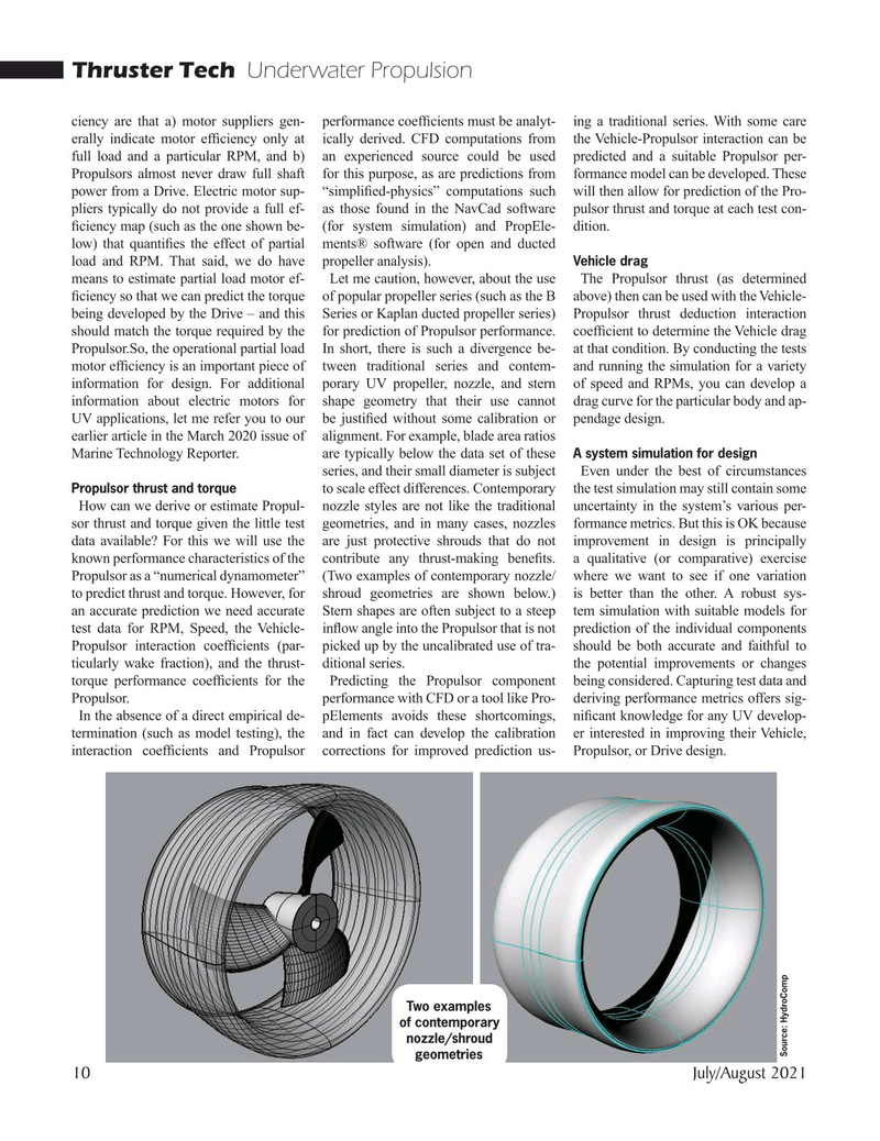
Propulsor as a “numerical dynamometer” (Two examples of contemporary nozzle/ where we want to see if one variation to predict thrust and torque. However, for shroud geometries are shown below.) is better than the other. A robust sys- an accurate prediction we need accurate Stern shapes are often subject to a steep tem simulation with suitable models for test data for RPM, Speed, the Vehicle- in? ow angle into the Propulsor that is not prediction of the individual components
Propulsor interaction coef? cients (par- picked up by the uncalibrated use of tra- should be both accurate and faithful to ticularly wake fraction), and the thrust- ditional series. the potential improvements or changes torque performance coef? cients for the Predicting the Propulsor component being considered. Capturing test data and
Propulsor. performance with CFD or a tool like Pro- deriving performance metrics offers sig-
In the absence of a direct empirical de- pElements avoids these shortcomings, ni? cant knowledge for any UV develop- termination (such as model testing), the and in fact can develop the calibration er interested in improving their Vehicle, interaction coef? cients and Propulsor corrections for improved prediction us- Propulsor, or Drive design.
Two examples of contemporary nozzle/shroud
Source: HydroComp geometries 10 July/August 2021
MTR #5 (1-17).indd 10 7/30/2021 12:38:49 PM