
Page 21: of Maritime Reporter Magazine (March 1969)
Read this page in Pdf, Flash or Html5 edition of March 1969 Maritime Reporter Magazine
 20
20
 22
22
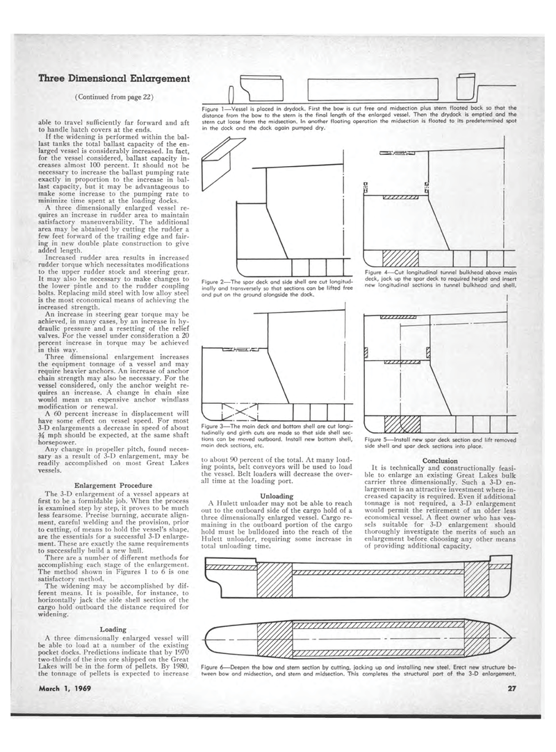
Three Dimensional Enlargement (Continued from page 22) able to travel sufficiently far forward and aft to handle hatch covers at the ends. If the widening is performed within the bal-last tanks the total ballast capacity of the en-larged vessel is considerably increased. In fact, for the vessel considered, ballast capacity in-creases almost 100 percent. It should not be necessary to increase the ballast pumping rate exactly in proportion to the increase in bal-last capacity, but it may be advantageous to make some increase to the pumping rate to minimize time spent at the loading docks. A three dimensionally enlarged vessel re-quires an increase in rudder area to maintain satisfactory maneuverability. The additional area may be abtained by cutting the rudder a few feet forward of the trailing edge and fair-ing in new double plate construction to give added length. Increased rudder area results in increased rudder torque which necessitates modifications to the upper rudder stock and steering gear. It may also be necessary to make changes to the lower pintle and to the rudder coupling bolts. Replacing mild steel with low alloy steel is the most economical means of achieving the increased strength. An increase in steering gear torque may be achieved, in many cases, by an increase in hy-draulic pressure and a resetting of the relief valves. For the vessel under consideration a 20 percent increase in torque may be achieved in this way. Three dimensional enlargement increases the equipment tonnage of a vessel and may require heavier anchors. An increase of anchor chain strength may also be necessary. For the vessel considered, only the anchor weight re-quires an increase. A change in chain size would mean an expensive anchor windlass modification or renewal. A 60 percent increase in displacement will have some effect on vessel speed. For most 3-D enlargements a decrease in speed of about mph should be expected, at the same shaft horsepower. Any change in propeller pitch, found neces-sary as a result of 3-D enlargement, may be readily accomplished on most Great Lakes vessels. Enlargement Procedure The 3-D enlargement of a vessel appears at first to be a formidable job. When the process is examined step by step, it proves to be much less fearsome. Precise burning, accurate align-ment, careful welding and the provision, prior to cutting, of means to hold the vessel's shape, are the essentials for a successful 3-D enlarge-ment. These are exactly the same requirements to successfully build a new hull. There are a number of different methods for accomplishing each stage of the enlargement. The method shown in Figures 1 to 6 is one satisfactory method. The widening may be accomplished by dif-ferent means. It is possible, for instance, to horizontally jack the side shell section of the cargo hold outboard the distance required for widening. Loading A three dimensionally enlarged vessel will be able to load at a number of the existing pocket docks. Predictions indicate that by 1970 two-thirds of the iron ore shipped on the Great Lakes will be in the form of pellets. By 1980, the tonnage of pellets is expected to increase Figure 1?Vessel is placed in drydock. First the bow is cut free and midsection plus stern floated back so that the distance from the bow to the stern is the final length of the enlarged vessel. Then the drydock is emptied and the stern cut loose from the midsection. In another floating operation the midsection is floated to its predetermined spot in the dock and the dock again pumped dry. Figure 2?The spar deck and side shell are cut longitud-inally and transversely so that sections can be lifted free and put on the ground alongside the dock. Figure 3?The main deck and bottom shell are cut longi-tudinally and girth cuts are made so that side shell sec-tions can be moved outboard. Install new bottom shell, main deck sections, etc. to about 90 percent of the total. At many load-ing points, belt conveyors will be used to load the vessel. Belt loaders will decrease the over-all time at the loading port. Unloading A Hulett unloader may not be able to reach out to the outboard side of the cargo hold of a three dimensionally enlarged vessel. Cargo re-maining in the outboard portion of the cargo hold must be bulldozed into the reach of the Hulett unloader, requiring some increase in total unloading time. SI fcl -zzzzzzzzr 'A Figure 4?Cut longitudinal tunnel bulkhead above main deck, jack up the spar deck to required height and insert new longitudinal sections in tunnel bulkhead and shell. Figure 5?Install new spar deck section and lift removed side shell and spar deck sections into place. Conclusion It is technically and constructionally feasi-ble to enlarge an existing Great Lakes bulk carrier three dimensionally. Such a 3-D en-largement is an attractive investment where in-creased capacity is required. Even if additional tonnage is not required, a 3-D enlargement would permit the retirement of an older less economical vessel. A fleet owner who has ves-sels suitable for 3-D enlargement should thoroughly investigate the merits of such an enlargement before choosing any other means of providing additional capacity. Figure 6?Deepen the bow and stern section by cutting, jacking up and installing new steel. Erect new structure be-tween bow and midsection, and stern and midsection. This completes the structural part of the 3-D enlargement. March 1, 1969 27
