Page 24: of Maritime Reporter Magazine (March 15, 1969)
Read this page in Pdf, Flash or Html5 edition of March 15, 1969 Maritime Reporter Magazine
 23
23
 25
25
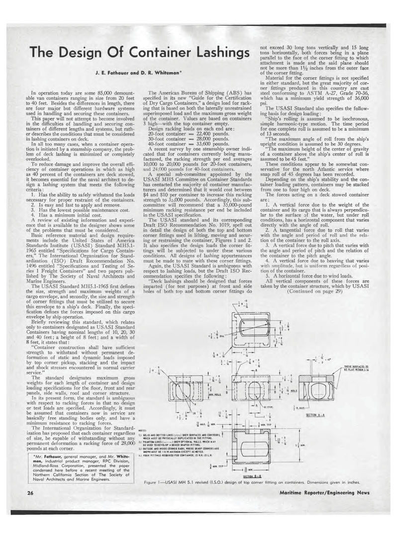
The Design Of Container Lashings J. E. Fathauer and D. R. Whiteman' In operation today are some 85,000 demount-able van containers ranging in size from 20 feet to 40 feet. Besides the differences in length, there are four major but different hardware systems used in handling and securing these containers. This paper will not attempt to become involved in the difficulties of handling and securing con-tainers of different lengths and systems, but rath-er describes the conditions that must be considered in lashing containers on deck. In all too many cases, when a container opera-tion is initiated by a steamship company, the prob-lem of deck lashing is minimized or completely overlooked. To reduce damage and improve the overall effi-ciency of container operations in which as high as 40 percent of the containers are deck stowed, it becomes essential for the naval architect to de-sign a lashing system that meets the following criteria: 1. Has the ability to safely withstand the loads necessary for proper restraint of the containers. 2. Is easy and fast to apply and remove. 3. Has the lowest possible maintenance cost. 4. Has a minimum initial cost. A review of existing information and experi-ence that is available to the designer shows some of the problems that must be considered. Basic reference material and design require-ments include the United States of America Standards Institute (USASI) Standard MH5.1-1965 entitled "Specifications for Cargo Contain-ers," The International Organization for Stand-ardization (ISO) Draft Recommendation No. 1496 entitled "Specifications and Testing of Se-ries 1 Freight Containers" and two papers pub-lished by The Society of Naval Architects and Marine Engineers. The USASI Standard MH5.1-1965 first defines the size, strength and maximum weights of a cargo envelope, and secondly, the size and strength of corner fittings that must be utilized to secure this envelope to a ship's deck. Finally, the speci-fication defines the forces imposed on this cargo envelope by ship operation. Briefly reviewing this standard, which relates only to containers designated as USASI Standard Containers having nominal lengths of 10, 20, 30 and 40 feet; a height of 8 feet; and a width of 8 feet, it states that: "Container construction shall have sufficient strength to withstand without permanent de-formation of static and dynamic loads imposed by top corner pickup, stacking and the impact and shock stresses encountered in normal carrier service." The standard designates maximum gross weights for each length of container and design loading specifications for the floor, front and rear panels, side walls, roof and corner structure. In its present form, the standard is ambiguous with respect to racking forces in that no design or test loads are specified. Accordingly, it must be assumed that containers now in service are basically free standing bodies only, and have a minimum resistance to racking forces. The International Organization for Standard-ization has proposed that each container regardless of size, be eapable of withstanding without any permanent deformation a racking force of 28,000 pounds at each corner. The American Bureau of Shipping (ABS) has specified in its new "Guide for the Certification of Dry Cargo Containers," a design load for rack-ing that is based on both the laterally unrestrained superimposed load and the maximum gross weight of the container. Values are based on containers 3 high?with the top container empty. Design racking loads on each end are: 20-foot container = 22,400 pounds. 30-foot container = 28,000 pounds. 40-foot container = 33,600 pounds. A recent survey by one steamship owner indi-cated that for containers currently being manu-factured, the racking strength per end averages 10,000 to 20,000 pounds for 20-foot containers, and 24.000 pounds for 40-foot containers. A special sub-committee appointed by the USASI MH5 Committee on Container Standards has contacted the majority of container manufac-turers and determined that it would cost between $4 and $10 per container to increase this racking strength to 3o,000 pounds. Accordingly, this sub-committee will recommend that a 35,000-pound minimum racking resistance per end be included in the USASI specification. The USASI standard and its corresponding Draft ISO Recommendation No. 1019, spell out in detail the design of both the top and bottom corner fittings used in lifting, moving and secur-ing or restraining the container, Figures 1 and 2. It also specifies the design loads the corner fit-tings will be subjected to under these various conditions. All designs of lashing appurtenances must be made to mate with these corner fittings. Again, the USASI Standard is ambiguous with respect to lashing loads, but the Draft ISO Rec-ommendation specifies the following: "Deck lashings should be designed that forces imparted (for test purposes) at front and side holes of both top and bottom corner fittings do not exceed 30 long tons vertically and 15 long tons horizontally, both forces being in a plane parallel to the face of the corner fitting to which attachment is made and the said plane should not be more than inches from the outer face of the corner fitting. Material for the corner fittings is not specified in either standard, but the great majority of cor-ner fittings produced in this country are cast steel conforming to ASTM A-27, Grade 70-36, which has a minimum yield strength of 36,000 psi. The USASI Standard also specifies the follow-ing basis for design loading: "Ship's rolling is assumed to be isochronous, simple harmonic-type motion. The time period for one complete roll is assumed to be a minimum of 13 seconds. "The maximum angle of roll from the ship's upright condition is assumed to be 30 degrees. "The maximum height of the center of gravity of a container above the ship's center of roll is assumed to be 45 feet." These conditions appear to be somewhat con-servative for the north Atlantic service where snap roll of 45 degrees has been recorded. Depending on the ship's stability and the con-tainer loading pattern, containers may be stacked from one to four high on deck. The forces acting on a deck stowed container are: 1. A vertical force due to the weight of the container and its cargo that is always perpendicu-lar to the surface of the water, but under roll conditions, has a horizontal component that varies directly with the angle of roll. 2. A tangential force due to roll that varies with the angle and period of roll and the rela-tion of the container to the roll axis. 3. A vertical force due to pitch that varies with the angle and period of pitch and the relation of the container to the pitch angle. 4. A vertical force due to heaving that varies with amplitude, but is uniform regardless of posi-tion of the container. 5. A horizontal force due to wind loads. All vertical components of these forces are taken by the container structure, which by USASI (Continued on page 29) *Mr. Fathauer, general manager, and Mr. White-man, industrial product manager, RPC Division, Midland-Ross Corporation, presented the paper condensed here before a recent meeting of the Northern California Section of The Society of Naval Architects and Marine Engineers. THESE SURFACES TO BE FLAT WITHIN 1. I* HOTES I.I SOLID AND DOTTED LINES SHOW SURFACES AND CONTOURS. WHICH MUST BE PHYSICALLY DUPLICATED IN THE FITTING. 2.1 PHANTOM LINES! 1 SHOWOPTIONAL WALLS, WHICH MAY BE USED TO DEVELOP A BOXED SHAPED FITTING 3.1 OUTSIDE AND INSIDE CORNER RADII, WHERE SHARP CORNERS ARE SHOWN MUST BE I I IN.MAXIMUM EXCEPT AS NOTED. 4.1 FOUR FITTINGS REQUIRED PER CONTAINER. 121 R.H. 121 L.H. SECTION B-B Figure 1?USASI MH 5.1 revised (I.S.O.) design of top corner fitting on containers. Dimensions given in inches. 26 Maritime Reporter/Engineering News
