Page 27: of Maritime Reporter Magazine (March 15, 1969)
Read this page in Pdf, Flash or Html5 edition of March 15, 1969 Maritime Reporter Magazine
 26
26
 28
28
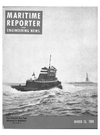
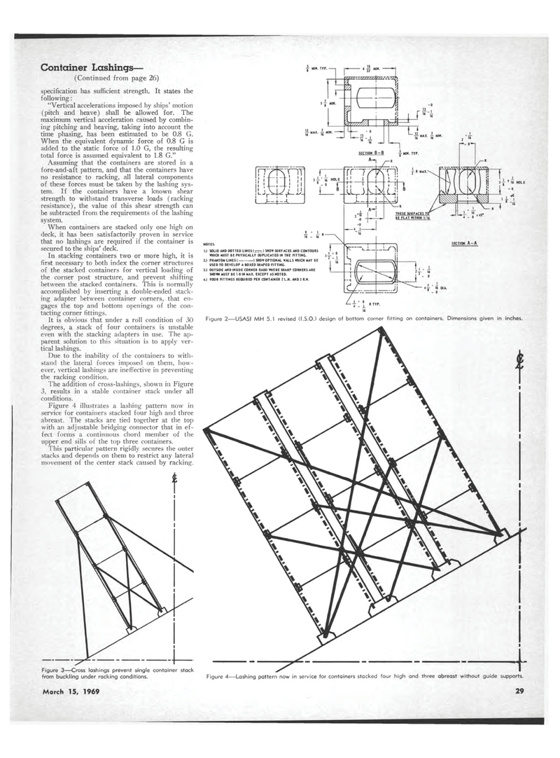
Container Lashings? (Continued from page 26) specification has sufficient strength. It states the following: "Vertical accelerations imposed by ships' motion (pitch and heave) shall be allowed for. The maximum vertical acceleration caused by combin-ing pitching and heaving, taking into account the time phasing, has been estimated to be 0.8 G. When the equivalent dynamic force of 0.8 G is added to the static force of 1.0 G, the resulting total force is assumed equivalent to 1.8 G." Assuming that the containers are stored in a fore-and-aft pattern, and that the containers have no resistance to racking, all lateral components of these forces must be taken by the lashing sys-tem. If the containers have a known shear strength to withstand transverse loads (racking resistance), the value of this shear strength can be subtracted from the requirements of the lashing system. When containers are stacked only one high on deck, it has been satisfactorily proven in service that no lashings are required if the container is secured to the ships' deck. In stacking containers two or more high, it is first necessary to both index the corner structures of the stacked containers for vertical loading of the corner post structure, and prevent shifting between the stacked containers. This is normally accomplished by inserting a double-ended stack-ing adapter between container corners, that en-gages the top and bottom openings of the con-tacting corner fittings. It is obvious that under a roll condition of 30 degrees, a stack of four containers is unstable even with the stacking adapters in use. The ap-parent solution to this situation is to apply ver-tical lashings. Due to the inability of the containers to with-stand the lateral forces imposed on them, how-ever, vertical lashings are ineffective in preventing the racking condition. The addition of cross-lashings, shown in Figure 3, results in a stable container stack under all conditions. Figure 4 illustrates a lashing pattern now in service for containers stacked four high and three abreast. The stacks are tied together at the top with an adjustable bridging connector that in ef-fect forms a continuous chord member of the upper end sills of the top three containers. This particular pattern rigidly secures the outer stacks and depends on them to restrict any lateral movement of the center stack caused by racking. from buckling under racking conditions. March 15, 1969 29 Figure 2?USASI MH 5.1 revised (I.S.O.) design of bottom corner fitting on containers. Dimensions given in inches. Figure 4?Lashing pattern now in service for containers stacked four high and three abreast without guide supports. y MIN. TYP. 7 1 1 " TYf-16 £ MAX. i MIN. SECTION ft-A 3 J-* 14 HOLE ' - 0 J_ x ' 14 HOI E NOTES: 1.1 SOLID AND DOTTED LINES(=-=r) SHOW SURFACES AND CONTOURS WHICH MUST BE PHYSICALLY DUPLICATED IN THE FITTING. 2.) PHANTOM LINESI ) SHOW OPTIONAL WALLS WHICH MAY BE USED TO DEVELOP A BOXED SHAPED FITTING. 3.) OUTSIDE AND INSIDE CORNER RADII WHERE SHARP CORNERS ARE SHOWN MUST BE 1/8 IN MAX. EXCEPT AS NOTED. 4.1 FOUR FITTINGS REQUIRED PER CONTAINER 2L.H. AND 2 R.H.
