
Page 35: of Maritime Reporter Magazine (December 15, 1970)
Read this page in Pdf, Flash or Html5 edition of December 15, 1970 Maritime Reporter Magazine
 34
34
 36
36
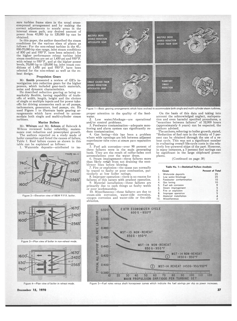
Figure 1 —Basic gearing arrangements which have evolved to accommodate both single and multi-cylinder steam turbines. sure turbine frame sizes in the usual cross- compound arrangement and by making the correct adjustments to nozzle areas in the internal steam path, any desired amount of power from 45,000 hp to 120,000 hp can be obtained.
In this paper, the author described the steam conditions for the various sizes of plants as follows: For the non-reheat turbine in the 45,- 000-70,000-hp size range, inlet steam conditions of 850 psi and 950°F. have been selected; for the higher performance reheat turbine inlet steam conditions are set at 1,450 psi and 950°F. with reheat to 950°F., and at the higher power levels, 70,000 hp to 120,000 hp, inlet steam con- ditions of 1,450 psi and 950°F. have been selected for the non-reheat as well as the re- heat design.
Propulsion Gears
Mr. Smith presented a review of GE's in- vestigation into reduction gears for the higher powers, which included gear-teeth materials, noise and dynamic characteristics.
He described reduction gearing as being re- markably flexible, having capability of trade- offs of width, length, height and the choices of single or multiple inputs and for power take- offs for driving accessories such as oil pumps, tachometers, generators, feed pumps, etc. He used Figure 1 to illustrate basic gearing ar- rangements which have evolved to accom- modate both single and multi-cylinder steam turbines.
Marine Boilers
Mr. Whitam and Mr. Schoen of Babcock &
Wilcox reviewed boiler reliability, mainte- nance cost reduction and powerplant growth.
The authors reported on a study made of boiler casualties and listed the causes of failure,
Table 1. Real failure causes as shown in this table can be explained as follows: 1. Waterside deposits—attributed to im- proper attention to the quality of the feed- water. 2. Low water/blockage—are operational and/or control problems. 3. Feedwater contamination—adequate mon- itoring and alarm system can significantly re- duce contamination. 4. Gas laning—this has been a problem where wide openings are left between adjacent superheater tube rows at steam pass separation areas. 5. Fuel ash corrosion—over 90 percent of these failures were in the main generating bank. They are the result of sulfur-laden soot accumulations over the water drum. 6. Steam impingement—-these failures more than likely result from not draining the soot- blower lines before blowing. 7. Fire or explosion—the cause can normally be traced to faulty or poor combustion, par- ticularly at low boiler ratings. 8. Improper operation—there is no reason for failures of this nature with prudent operation. 9. Material installation—these failures are primarily due to such things as faulty welds or poor workmanship. 10. Miscellaneous—these failures are due to steam-side corrosion, water-side corrosion, oxygen corrosion and water-side or fire-side abrasion.
On the basis of this data and taking into account the acknowledged neglect, malopera- tion and even harmful specified procedures, a "meantime between failures" of 52,000 hours (approximately 6 years) can be expected, the authors advised.
The authors, referring to boiler growth, stated, "Reduction of fuel rate in the vicinity of 5 per- cent can be obtained through the use of a re- heat cycle. This was not a significant number in evaluating overall life-cycle costs in the rela- tively low-powered ships of the past. However, in many instances, a 5 percent fuel savings can be significant in the large shipboard power- plants. (Continued on page 38)
Table No. 1—Statistical Failure Analysis
Cause Percent of Total 1. Waterside deposits 25 2. Low water/blockage 3. Feedwater contamination 10 4. Gas laning 1 5. Fuel ash corrosion 9 6. Steam impingement 5 7. Fire or explosion 8. Improper operation 9. Material installation 4 10. Miscellaneous 2
Figure 4—Plan view of boiler in reheat mode.
December 15, 1970 x. m
GO _i
UJ
MST-13 NON-REHEAT 850G - 950*F
MST-14 NON-REHEAT 850 6 - 950 °F i tiMfl wMmfflMm- _ MST-14 NON-REHEAT (t) 1450 6-950 8 F ..I I L. @ MST-14 REHEAT 1450 6 - 950/950#F
E5 — ™II'HIWI|||IBH ,1 L, ; t t i 1 J L J i 10 20 30 40 50 60 70 80 90 100 110 120
MAIN PROPULSION SHP/1000 PER TURBINE SET
Figure 5—Fuel rates versus shaft horsepower curves which indicate the fuel savings per shp as power increases. 37
Figure 3—Plan view of boiler in non-reheat mode.
