Page 6: of Maritime Reporter Magazine (June 15, 1971)
Read this page in Pdf, Flash or Html5 edition of June 15, 1971 Maritime Reporter Magazine
 5
5
 7
7
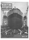
Shipbuilding Basin—The largest shipbuilding basin in this hemisphere is 1,200 feet long and 200 feet wide, covers 514 acres and has room enough to build vessels up to 300,000 dwt. The basin was flooded just prior to the dedication ceremonies.
Sansinena II— (Continued from page 7) for firefighting. The 16-inch-di- ameter saltwater line of this sys- tem is on the side walls of the structure, 5 feet above the floor.
All the pumps and wet wells are located at the south entrances of the dock, with the pumping station entirely below ground level.
The pressure-relief system is de- signed to discharge water from around and under the structure at all times—even when it is flooded.
This will keep water from exerting any appreciable uplift on the bot- tom of the floor or behind the walls.
The pumps in this system start when the water elevation in the wet well reaches the underside of the floor slab. However, the dead- weight of the slab can withstand 7 to 8 feet of hydrostatic head.
The floor of the basin is designed to support line loading of 50 long tons exerted by the keel blocks on strips of slab 20 feet wide. It also is capable of carrying a concen- trated load of 20 tons on an 8-foot- square grid system outside of the area loaded by the keel blocks.
Four 100 - ton - capacity tower cranes, two on each side, will pro- vide the lifting capability for the fa- cility. Operated electrically, these cranes will reach halfway across the basin at maximum capacity.
When operated together, they can lift a subassembly that measures a maximum of 120 feet square and weighs 400 tons. The railways for the cranes are 40 feet wide. They are placed as close to the edge of the basin as possible to permit the maximum reach. The inside rail is at the top of the basin side wall, and the outside rail is supported on a continuously reinforced concrete beam and footing, which is on the fill behind the wall.
Mechanical and electrical utilities to serve the basin are in a service tunnel that runs along each side of the structure behind the side walls.
The tunnel also functions as a serv- ice gallery with windows provided on 100-foot centers where utility connections are provided. The elec- trical facilities for the tower cranes are in the ceiling of the tunnels, and a 4 inch wide longitudinal slot in the tunnel roof provides access for the crane collector arms.
The service tunnel also carries a 4-inch-diameter freshwater line and a 6-inch-diameter compressed-air line. Oxygen and acetylene lines are along the basin walls for easy access.
One 4,000-kva electrical substa- tion is provided on each side of the dock. Access to these stations and to the underground pumping sta- tion is via the service tunnel.
The basin is illuminated by a series of weatherproof mercury- vapor lights mounted on the inside of the side walls.
Eight 40-ton electrically oper- ated capstans, located on the sides of the basin, will aid in launching a ship. A 65-ton capstan, located on the centerline of the head wall, is intended for pulling a ship into the clock. However, this latter pro- cedure is not anticipated to be a normal operation.
Sixteen 40-ton bollards, eight on each side of the structure, also will aid in maneuvering a ship in and out. Two dolphins on the north side of the dock will provide a mooring facility.
Steel stairways at each corner of the basin at the inboard end will provide personnel access from the ground level to the floor below.
Other New Facilities
Also dedicated at the ceremonies were the new panel shop and the new blasting and coating building, part of the yard's improvement plan costing tens of millions of dol- lars. Both of these facilities are in operation.
Ship assemblies, weighing up to 200 tons each, can now be produced on a fully mechanized, partially automated basis in the new panel shop.
In this new facility, steel plates are machine welded into units of up to 60 feet by 60 feet. Further processing adds stiffeners and webs that make a subassembly up to 25 feet high.
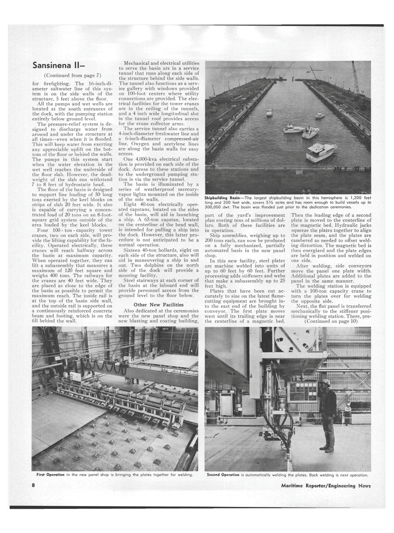
Plates that have been cut ac- curately to size on the latest flame- cutting equipment are brought in- to the east end of the building by conveyor. The first plate moves west until its trailing edge is near the centerline of a magnetic bed.
Then the leading edge of a second plate is moved to the centerline of the magnetic bed. Hydraulic jacks squeeze the plates together to align the plate seam, and the plates are cambered as needed to offset weld- ing distortion. The magnetic bed is then energized and the plate edges are held in position and welded on one side.
After welding, side conveyors move the panel one plate width.
Additional plates are added to the panel in the same manner.
The welding station is equipped with a 100-ton capacity crane to turn the plates over for welding the opposite side.
Next, the flat panel is transferred mechanically to the stiffener posi- tioning welding station. There, pre- (Continued on page 10)
First Operation in the new panel shop is bringing the plates together for welding. Second Operation is automatically welding the plates. Back welding is next operation. 8 Maritime Reporter/Engineering News
