Page 9: of Maritime Reporter Magazine (August 1973)
Read this page in Pdf, Flash or Html5 edition of August 1973 Maritime Reporter Magazine
 8
8
 10
10
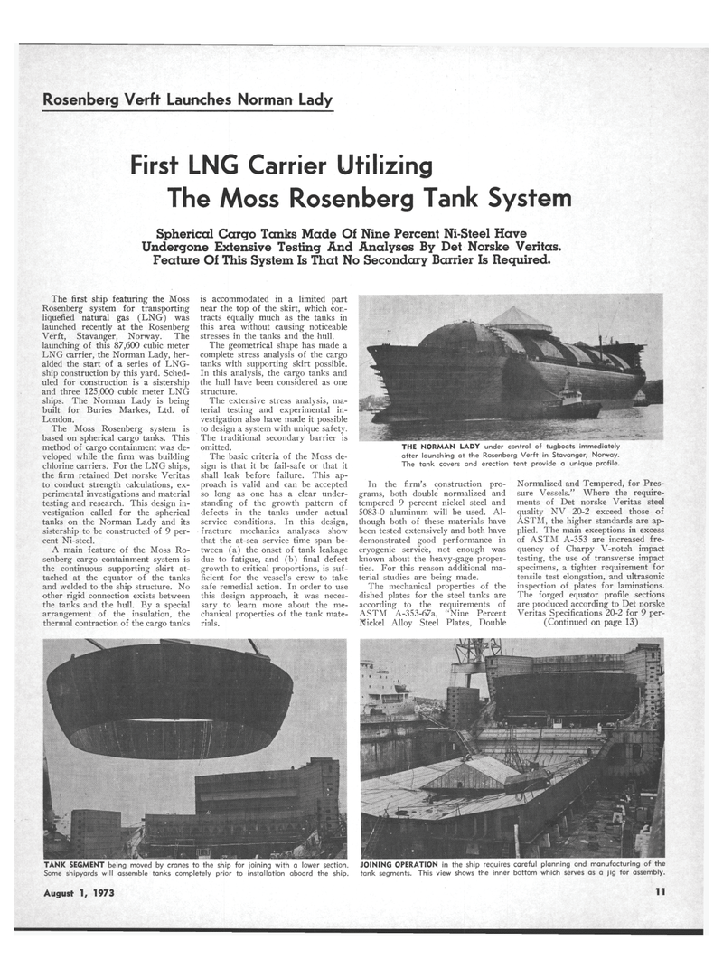
Rosenberg Verft Launches Norman Lady
First LNG Carrier Utilizing
The Moss Rosenberg Tank System
Spherical Cargo Tanks Made Of Nine Percent Ni-Steel Have
Undergone Extensive Testing And Analyses By Det Norske Veritas.
Feature Of This System Is That No Secondary Barrier Is Required.
THE NORMAN LADY under control of tugboats immediately after launching at the Rosenberg, Verft in Stavanger, Norway.
The tank covers and erection tent provide a unique profile.
The first ship featuring the Moss
Rosenberg system for transporting liquefied natural gas (LNG) was launched recently at the Rosenberg
Verft, Stavanger, Norway. The launching of this 87,600 cubic meter
LNG carrier, the Norman Lady, her- alded the start of a series of LNG- ship construction by this yard. Sched- uled for construction is a sistership and three 125,000 cubic meter LNG ships. The Norman Lady is being built for Buries Markes, Ltd. of
London.
The Moss Rosenberg system is based on spherical cargo tanks. This method of cargo containment was de- veloped while the firm was building chlorine carriers. For the LNG ships, the firm retained Det norske Veritas to conduct strength calculations, ex- perimental investigations and material testing and research. This design in- vestigation called for the spherical tanks on the Norman Lady and its sistership to be constructed of 9 per- cent Ni-steel.
A main feature of the Moss Ro- senberg cargo containment system is the continuous supporting skirt at- tached at the equator of the tanks and welded to the ship structure. No other rigid connection exists between the tanks and the hull. By a special arrangement of the insulation, the thermal contraction of the cargo tanks is accommodated in a limited part near the top of the skirt, which con- tracts equally much as the tanks in this area without causing noticeable stresses in the tanks and the hull.
The geometrical shape has made a complete stress analysis of the cargo tanks with supporting skirt possible.
In this analysis, the cargo tanks and the hull have been considered as one structure.
The extensive stress analysis, ma- terial testing and experimental in- vestigation also have made it possible to design a system with unique safety.
The traditional secondary barrier is omitted.
The basic criteria of the Moss de- sign is that it be fail-safe or that it shall leak before failure. This ap- proach is valid and can be accepted so long as one has a clear under- standing of the growth pattern of defects in the tanks under actual service conditions. In this design, fracture mechanics analyses show that the at-sea service time span be- tween (a) the onset of tank leakage due to fatigue, and (b) final defect growth to critical proportions, is suf- ficient for the vessel's crew to take safe remedial action. In order to use this design approach, it was neces- sary to learn more about the me- chanical properties of the tank mate- rials.
In the firm's construction pro- grams, both double normalized and tempered 9 percent nickel steel and 5083-0 aluminum will be used. Al- though both of these materials have been tested extensively and both have demonstrated good performance in cryogenic service, not enough was known about the heavy-gage proper- ties. For this reason additional ma- terial studies are being made.
The mechanical properties of the dished plates for the steel tanks are according to the requirements of
ASTM A-353-67a, "Nine Percent
Nickel Alloy Steel Plates, Double
Normalized and Tempered, for Pres- sure Vessels." Where the require- ments of Det norske Veritas steel quality NV 20-2 exceed those of
ASTM, the higher standards are ap- plied. The main exceptions in excess of ASTM A-353 are increased fre- quency of Charpy V-notch impact testing, the use of transverse impact specimens, a tighter requirement for tensile test elongation, and ultrasonic inspection of plates for laminations.
The forged equator profile sections are produced according to Det norske
Veritas Specifications 20-2 for 9 per- (Continued on page 13)
JOINING OPERATION in the ship requires careful planning and manufacturing of the tank segments. This view shows the inner bottom which serves as a jig for assembly.
TANK SEGMENT being moved by cranes to the ship for joining with a lower section.
Some shipyards will assemble tanks completely prior to installation aboard the ship.
August 1, 1973 11
