
Page 12: of Maritime Reporter Magazine (August 15, 1973)
Read this page in Pdf, Flash or Html5 edition of August 15, 1973 Maritime Reporter Magazine
 11
11
 13
13
Do Existing Regulations Properly Define
Requirements For Shafting Eccentricity?
Based On Naval And Merchant Standards For Main Propulsion Shafting
Eccentricity, One Is Underspecified And The Other Is Overly Restrictive
J.E. Ancarrow and R.L. Harrington*
There is an obvious requirement for acceptance criteria regarding de- sign tolerances for main propulsion shafting sections while the shafting is being manufactured; however, a less obvious type of requirement for such criteria, but one no less important, occurs when shafting becomes eccen- tric in service and a decision must be made to either take corrective ac- tion or to continue operation.
In the past, not only have the ac- ceptance criteria employed varied con- siderably in terms of sophistication, but also the implementation of the acceptance criteria has varied from formal procedures (those requiring no personal judgment) to informal procedures (which rely upon the con- sidered judgment of experienced per- sonnel). However, irrespective of the approach taken, there can be no doubt that all- acceptance criteria should be based on sound engineering fundamentals. This being the case, and recognizing that it is a practical impossibility to machine sections of shafting such that they are absolute- ly true and to also maintain them in this condition throughout their serv- ice life, it becomes necessary to estab- lish acceptance criteria for the eccen- tricities associated with propulsion shafting. *Mr. Ancarrow and Mr. Harrington of
Newport News Shipbuilding and Dry
Dock Company presented the paper con- densed here before a meeting of the
Hampton Roads Section of The Society of Naval Architects and Marine En- gineers.
Several different approaches may be taken to the problem of establish- ing eccentricity acceptance criteria.
The basic alternatives are as follows: 1. Insist upon the highest degree of precision that can possibly be achieved. 2. Require the highest degree of precision that can be achieved in a practical sense. 3. Determine the acceptance of an eccentricity measurement based on a comprehensive assessment of the ef- fects of the eccentricity under con- sideration.
From an ideal point of view, the tolerances for shafting should be suf- ficiently restrictive to ensure satisfac- tory performance in service, but should not be so restrictive as to in- crease costs unnecessarily. To impose excessively restrictive tolerances, rela- tive to those which are necessary to meet the functional requirements, can only lead to unusable quality which is not cost effective.
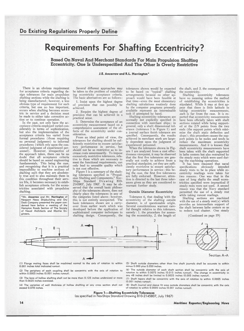
Figure 1 is a summary of the shaft- ing tolerances specified in "Propul- sion Shafting and Components," Nav-
Ships Standard Drawing 810- 2145807, July 1967. It may be ob- served that the overall basic philoso- phy of the tolerances shown, does not clearly place the tolerances in any of the categories listed above; however, this is not entirely unexpected. The basic tolerances shown are a carry- over from earlier work which was developed before the application of sophisticated computer techniques to shafting design. Consequently, the tolerances shown would be expected to be based on "typical" shafting arrangements because no other ap- proach would have been feasible at that time—even the most elementary shafting calculations routinely done by the computer programs presently available represent an interminable task if attempted by hand.
Shafting eccentricity tolerances are normally not explicitly specified in connection with merchant ships; in general, only a shaft dimensional tol- erance (tolerance 5 in Figure 1) and a journal surface finish tolerance are specified. Consequently, the results achieved in merchant work are large- ly dependent upon the judgment of experienced personnel.
When the tolerances shown in Fig- ure 1 are analyzed from a cost effec- tiveness viewpoint, it may be observed that the first five tolerances are gen- erally not costly to achieve from a practical standpoint, yet they are suffi- ciently restrictive to ensure satisfac- tory performance in service; tbis be- ing the case, the first five tolerances are fully endorsed. However, atten- tion is directed to the last three toler- ances given as they are considered to warrant further study.
Outside Diameter Eccentricity
Tolerance 6, that dealing with the eccentricity of the shafting outside diameter, is of questionable origin.
Several considerations warrant care- ful thought relative to this tolerance, namely: 1. the procedure for assess- ing the eccentricity, 2. the length of the shaft, and 3. the consequences of the eccentricity.
Shafting eccentricity tolerances have no meaning unless the method of establishing the eccentricities is stipulated. While it may at first ap- pear that there is little latitude in taking eccentricity measurements, such is far from the case. It is re- ported that eccentricity measurements have been officially taken with shaft sections rotated while being support- ed at the 2/9 points from the two ends (the support points which mini- mize the shaft static deflection and slope) ; this procedure causes the sup- port points to be nodes and tends to reduce the maximum eccentricity measurements. And it is known that shaft eccentricity measurements have been taken with the shaft supported in lathe centers but also restrained by the steady rests which were used dur- ing the machining operations.
It has been reasoned that naval specifications obviously intended steady rests to be in place while ec- centricity readings were taken for two reasons: One was that in the case of long shafts the small eccen- tricities specified were impractical if steady rests were not used. A second reason was that the Navy standard permitted the use of a steady rest while taking runout readings.
Shafting sections are machined with the use of a steady rest(s) which provides an intermediate support of the shaft between lathe centers so as to reduce tool chatter. One steady (Continued on page 19) 4 -i (1) Flange mating faces shall be machined normal to the axis of rotation to within 0.001 inches total indicated runout. (2) The periphery of each coupling shall be concentric with the axis of rotation to within 0.0005 inches (0.001 inches runout). (3) The bore of hollow shafting shall not be more than 0.125 inches undersized or more than 0.0625 inches oversized. (4) The variation of wall thickness of hollow shafting at any cross section shall not exceed 0.078 inches.
Section A-A (5) Shaft outside diameters other than line shaft journals shall be accurate to within minus 0.000 plus 0.050 inches. (6) The outside diameter of each shaft section shall be concentric with the axis of rotation to within 0.0075 inches (0.015 inches runout). The change in eccentricity in any 48 inches shall be limited to 0.0025 inches (0.005 inches runout). (7) Shaft tapers shall be concentric with the axis of rotation to within 0.0005 inches (0.001 inches runout). (8) Shaft Journal and sleeve fit area outside diameters shall be concentric with the axis of rotation to within 0.0005 inches (0.001 inches runout).
Figure 1—Shafting Eccentricity Tolerances (as specified in NavShips Standard Drawing 810-2145807, July 1967) 14
Maritime Reporter/Engineering News
