
Page 15: of Maritime Reporter Magazine (August 15, 1973)
Read this page in Pdf, Flash or Html5 edition of August 15, 1973 Maritime Reporter Magazine
 14
14
 16
16
Shafting Eccentricity— (Continued from page 14) rest is generally used on short shafts (shafts up to about 30 feet long), whereas two steady rests are required on longer shafts such as stern tube and propeller shafts.
The machining process is begun by locating the rough work in lathe cen- ters, then with the shaft allowed to sag freely, a cut is made at the steady rest positions desired. When a smooth surface is obtained, the steady rest is put in place and shifted to posi- tion the shaft in a straight line. Then the remaining length of the shaft can be cut without tool chatter.
After each cut, there is a possibility that the material removed from the shaft may have contained residual stresses such that their removal would have tended to cause the shaft to bow; consequently, the steady rests must be removed so that the steady rest positions can be checked and corrected as required. If these steps are not carefully followed, it is pos- sible to machine a shaft that is per- fectly true with a steady rest in place, but in fact contain a significant bow when the steady rest is removed. This consideration has been recognized by
NavSec personnel, and it is reported that the use of steady rests when taking eccentricity measurements will not be permitted by the next revision of the NavShips Standard.
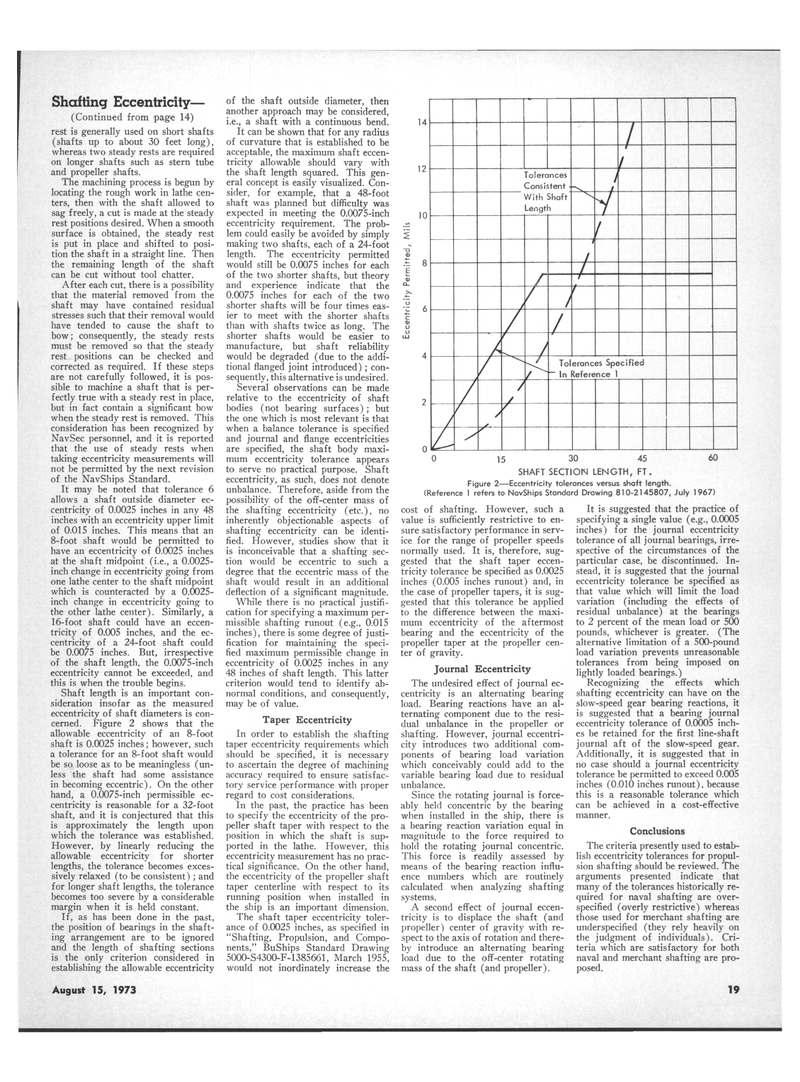
It may be noted that tolerance 6 allows a shaft outside diameter ec- centricity of 0.0025 inches in any 48 inches with an eccentricity upper limit of 0.015 inches. This means that an 8-foot shaft would be permitted to have an eccentricity of 0.0025 inches at the shaft midpoint (i.e., a 0.0025- inch change in eccentricity going from one lathe center to the shaft midpoint which is counteracted by a 0.0025- inch change in eccentricity going to the other lathe center). Similarly, a 16-foot shaft could have an eccen- tricity of 0.005 inches, and the ec- centricity of a 24-foot shaft could be 0.0075 inches. But, irrespective of the shaft length, the 0.0075-inch eccentricity cannot be exceeded, and this is when the trouble begins.
Shaft length is an important con- sideration insofar as the measured eccentricity of shaft diameters is con- cerned. Figure 2 shows that the allowable eccentricity of an 8-foot shaft is 0.0025 inches; however, such a tolerance for an 8-foot shaft would be so loose as to be meaningless (un- less the shaft had some assistance in becoming eccentric). On the other hand, a 0.0075-inch permissible ec- centricity is reasonable for a 32-foot shaft, and it is conjectured that this is approximately the length upon which the tolerance was established.
However, by linearly reducing the allowable eccentricity for shorter lengths, the tolerance becomes exces- sively relaxed (to be consistent) ; and for longer shaft lengths, the tolerance becomes too severe by a considerable margin when it is held constant.
If, as has been done in the past, the position of bearings in the shaft- ing arrangement are to be ignored and the length of shafting sections is the only criterion considered in establishing the allowable eccentricity of the shaft outside diameter, then another approach may be considered, i.e., a shaft with a continuous bend.
It can be shown that for any radius of curvature that is established to be acceptable, the maximum shaft eccen- tricity allowable should vary with the shaft length squared. This gen- eral concept is easily visualized. Con- sider, for example, that a 48-foot shaft was planned but difficulty was expected in meeting the 0.0075-inch eccentricity requirement. The prob- lem could easily be avoided by simply making two shafts, each of a 24-foot length. The eccentricity permitted would still be 0.0075 inches for each of the two shorter shafts, but theory and experience indicate that the 0.0075 inches for each of the two shorter shafts will be four times eas- ier to meet with the shorter shafts than with shafts twice as long. The shorter shafts would be easier to manufacture, but shaft reliability would be degraded (due to the addi- tional flanged joint introduced); con- sequently, this alternative is undesired.
Several observations can be made relative to the eccentricity of shaft bodies (not bearing surfaces) ; but the one which is most relevant is that when a balance tolerance is specified and journal and flange eccentricities are specified, the shaft body maxi- mum eccentricity tolerance appears to serve no practical purpose. Shaft eccentricity, as such, does not denote unbalance. Therefore, aside from the possibility of the off-center mass of the shafting eccentricity (etc.), no inherently objectionable aspects of shafting eccentricity can be identi- fied. However, studies show that it is inconceivable that a shafting sec- tion would be eccentric to such a degree that the eccentric mass of the shaft would result in an additional deflection of a significant magnitude.
While there is no practical justifi- cation for specifying a maximum per- missible shafting runout (e.g., 0.015 inches), there is some degree of justi- fication for maintaining the speci- fied maximum permissible change in eccentricity of 0.0025 inches in any 48 inches of shaft length. This latter criterion would tend to identify ab- normal conditions, and consequently, may be of value.
Taper Eccentricity
In order to establish the shafting taper eccentricity requirements which should be specified, it is necessary to ascertain the degree of machining accuracy required to ensure satisfac- tory service performance with proper regard to cost considerations.
In the past, the practice has been to specify the eccentricity of the pro- peller shaft taper with respect to the position in which the shaft is sup- ported in the lathe. However, this eccentricity measurement has no prac- tical significance. On the other hand, the eccentricity of the propeller shaft taper centerline with respect to its running position when installed in the ship is an important dimension.
The shaft taper eccentricity toler- ance of 0.0025 inches, as specified in "Shafting, Propulsion, and Compo- nents," BuShips Standard Drawing 5000-S4300-F-1385661, March 1955, would not inordinately increase the 14 12 10 to 2
E o
O- o •Z 6 c d) o o
LU 4 2 0 0 15 cost of shafting. However, such a value is sufficiently restrictive to en- sure satisfactory performance in serv- ice for the range of propeller speeds normally used. It is, therefore, sug- gested that the shaft taper eccen- tricity tolerance be specified as 0.0025 inches (0.005 inches runout) and, in the case of propeller tapers, it is sug- gested that this tolerance be applied to the difference between the maxi- mum eccentricity of the aftermost bearing and the eccentricity of the propeller taper at the propeller cen- ter of gravity.
Journal Eccentricity
The undesired effect of journal ec- centricity is an alternating bearing load. Bearing reactions have an al- ternating component due to the resi- dual unbalance in the propeller or shafting. However, journal eccentri- city introduces two additional com- ponents of bearing load variation which conceivably could add to the variable bearing load due to residual unbalance.
Since the rotating journal is force- ably held concentric by the bearing when installed in the ship, there is a bearing reaction variation equal in magnitude to the force required to hold the rotating journal concentric.
This force is readily assessed by means of the bearing reaction influ- ence numbers which are routinely calculated when analyzing shafting systems.
A second effect of journal eccen- tricity is to displace the shaft (and propeller) center of gravity with re- spect to the axis of rotation and there- by introduce an alternating bearing load due to the off-center rotating mass of the shaft (and propeller). 45 60
It is suggested that the practice of specifying a single value (e.g., 0.0005 inches) for the journal eccentricity tolerance of all journal bearings, irre- spective of the circumstances of the particular case, be discontinued. In- stead, it is suggested that the journal eccentricity tolerance be specified as that value which will limit the load variation (including the effects of residual unbalance) at the bearings to 2 percent of the mean load or 500 pounds, whichever is greater. (The alternative limitation of a 500-pound load variation prevents unreasonable tolerances from being imposed on lightly loaded bearings.)
Recognizing the effects which shafting eccentricity can have on the slow-speed gear bearing reactions, it is suggested that a bearing journal eccentricity tolerance of O.00O5 inch- es be retained for the first line-shaft journal aft of the slow-speed gear.
Additionally, it is suggested that in no case should a journal eccentricity tolerance be permitted to exceed 0.005 inches (O.OlO inches runout), because this is a reasonable tolerance which can be achieved in a cost-effective manner.
Conclusions
The criteria presently used to estab- lish eccentricity tolerances for propul- sion shafting should be reviewed. The arguments presented indicate that many of the tolerances historically re- quired for naval shafting are over- specified (overly restrictive) whereas those used for merchant shafting are underspecified (they rely heavily on the judgment of individuals). Cri- teria which are satisfactory for both naval and merchant shafting are pro- posed.
SHAFT SECTION LENGTH, FT.
Figure 2—Eccentricity tolerances versus shaft length. (Reference 1 refers to NavShips Standard Drawing 810-2145807, July 1967)
August 19, 1973 13
