
Page 10: of Maritime Reporter Magazine (September 1973)
Read this page in Pdf, Flash or Html5 edition of September 1973 Maritime Reporter Magazine
 9
9
 11
11
Avondale Shipyard Delivers
The Delta Mar (Continued from page 11) of the Delta Mar in South American waters
LASH vessels will be sailing to all six continents, and the LASH System can truly be said to have achieved world-wide service.
The design of the Delta Mar was developed by the naval architectural firm of Friede & Goldman,
Inc., and licensed for use to Delta Lines by
LASH Systems, Inc. Jerome L. Goldman, the inventor of LASH, is president of both LASH
Systems, Inc. and Friede & Goldman, Inc.
PRINCIPAL CHARACTERISTICS
Length Overall (Extreme) 893 feet
Breadth 100 feet
Design Draft 28 feet
Deadweight (At design draft), long tons 21,300
Scantling Draft 38 feet
Deadweight (At scantling draft), long tons 40,090
Normal Service Speed 22.4 knots
Shaft Horsepower, Continuous 32,000
Barge Capacity 74
Container Capacity, 20-foot 288
Barge Crane Capacity, long tons 455
Container Crane Capacity, long tons 30
Maximum Container Capacity, 20-foot 1,740
Crew Complement 33
GENERAL ARRANGEMENTS
Delta Mar has been constructed in accordance with the requirements of the American Bureau of Shipping to entitle her to the highest class for ships of this type, as well as conforming with the regulations of the Coast Guard.
The profile appearance of the Delta Mar is of the unique type in that the house is located well forward and the machinery located as far aft as possible. This arrangement permits the best part of the vessel to be used for the transport of cargo, and at the same time offers excellent protection for the on-deck stowage of lighters and con- tainers. Officers and crew members are quartered in the forward superstructure. The navigating bridge design is ultra-modern in appearance as well as offering 360 degree visibility. Clear, un- obstructed walkaround is provided on the entire bridge deck. Forward of the accommodations and bridge house a stores crane is located on the star- board side for quick and easy handling of stores into the second deck stowage space.
At the aftermost part of the vessel two canter- levers are located which allow the lighter crane to overtravel the vessel for off-loading and on- loading lighters over the stern. The container crane on-loads and off-loads containers over the port or starboard side of the vessel.
Both the lighter crane and the container crane work their respective lighters/containers simulta- neously, thus assuring rapid loading or discharg- ing of cargoes.
All holds are so arranged that complete access is had to all lighters and to the cell stow of the containers. All holds are so dimensioned that conversion from lighter to container or from con- tainer to lighter hold transport is a relatively simple matter, not requiring shipyard facilities.
Each of the holds, having from one to three vertical cells are secured for sea and on-deck lighter/container stow, by steel pontoon type hatch covers. Handling of the hatch covers is accom- plished by the LASH gantry crane in a matter of minutes. As the gantry lighter crane does not travel to the position of Hold No. 1, cell position
No. 1, the hatch cover for this cell is of the hy- draulic folding type.
To handle the lighters which transport 370 long tons of cargo, a gantry crane having a hoisting capacity of 455 long tons is provided and runs on rails mounted on both sides of the ship. This crane was manufactured by Morgan Engineering
Company of Alliance, Ohio. The crane legs are equipped with guides giving continuity with the cargo hold and stern guides. Lighters are lifted vertically or lowered along these guides either from water level or double bottom top up to the highest point. These guides insure that the lighter does not sway while the crane is traveling along the deck. A load frame is provided which is equipped with a latching device which clamps onto the lighter or hatch cover. A swell compen- sating device is also provided which allows for latching-on and latching-off a lighter while rela- tive motion between lighter and vessel is expe- rienced.
The lighters are secured in the holds as well as on deck -by a system of wedging.
PROPULSION MACHINERY
The Delta Mar is powered by one cross-com- pound propulsion unit of DeLaval design and manufacture, comprising a high-pressure ahead turbine, a low-pressure turbine including ahead and astern elements, and double-helical, double- reduction gears. The turbines are connected to the reduction gear through flexible, mechanical dental-type couplings. The units provide 32,000 shp to the propeller.
The thrust bearing is of the hydro-dynamic bearing having pivoted-pads of the Kingsbury
Inc. design and is located well aft of the reduction gear. Lubrication to this thrust is supplied from the lubrication system of the main-propulsion reduction gear. The bearing is of the horizontal double-equalizing type, having eight thrust shoes on each side of the thrust collar, which is integral with the thrust shaft. The estimated forward thrust load is 350,000 pounds and the total bear- ing area in square inches being 1,061.
Steam at 850 psi and 950° F is admitted to the h-p turbine inlet through the DeLaval throttle arrangement which incorporates hydraulic power assist features thus providing a means of inter- facing the ship's control system with the turbine ahead and astern control valves.
The condenser is a rectangular, peripheral-flow, single-pass unit. The condenser is arranged to support the 1-p turbine, being bolted rigidly to the 1-p turbine exhaust. Circulating water is sup- plied by a scoop injection method, along with a circulating pump for slow-speed operation and maneuvering.
Steam is generated by means of two Combus- tion Engineering single-cased welded-wall con- struction units, with oil burners located in the furnace roof. Each unit is composed of a steam drum and a water drum connected by a bank of inclined generating tubes. The units are further provided with floor-screen tubes which shield the
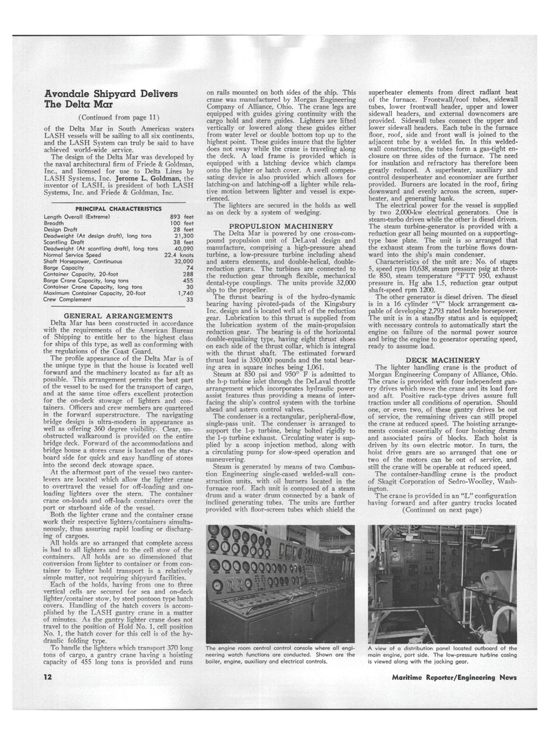
The engine room central control console where all engi- neering watch functions are conducted. Shown are the boiler, engine, auxiliary and electrical controls. superheater elements from direct radiant heat of the furnace. Frontwall/roof tubes, sidewall tubes, lower frontwall header, upper and lower sidewall headers, and external downcomers are provided. Sidewall tubes connect the upper and lower sidewall headers. Each tube in the furnace floor, roof, side and front wall is joined to the adjacent tube by a welded fin. In this welded- wall construction, the tubes form a gas-tight en- closure on three sides of the furnace. The need for insulation and refractory has therefore been greatly reduced. A superheater, auxiliary and control desuperheater and economizer are further provided. Burners are located in the roof, firing downward and evenly across the screen, super- heater, and generating bank.
The electrical power for the vessel is supplied by two 2,000-kw electrical generators. One is steam-turbo driven while the other is diesel driven.
The steam turbine-generator is provided with a reduction gear all being mounted on a supporting- type base plate. The unit is so arranged that the exhaust steam from the turbine flows down- ward into the ship's main condenser.
Characteristics of the unit are: No. of stages 5, speed rpm 10,638, steam pressure psig at throt- tle 850, steam temperature °FTT 950, exhaust pressure in. Hg abs 1.5, reduction gear output shaft-speed rpm 1200.
The other generator is diesel driven. The diesel is in a 16 cylinder "V" block arrangement ca- pable of developing 2,793 rated brake horsepower.
The unit is in a standby status and is equipped; with necessary controls to automatically start the engine on failure of the normal power source and bring the engine to generator operating speed, ready to assume load.
DECK MACHINERY
The lighter handling crane is the product of
Morgan Engineering Company of Alliance, Ohio.
The crane is provided with four independent gan- try drives which move the crane and its load fore and aft. Positive rack-type drives assure full traction under all conditions of operation. Should one, or even two, of these gantry drives be out of service, the remaining drives can still propel the crane at reduced speed. The hoisting arrange- ments consist essentially of four hoisting drums and associated pairs of blocks. Each hoist is driven by its own electric motor. In turn, the hoist drive gears are so arranged that one or two of the motors can be out of service, and still the crane will be operable at reduced speed.
The container-handling crane is the product of Skagit Corporation of Sedro-Woolley, Wash- ington.
The crane is provided in an "L" configuration having forward and after gantry trucks located (Continued on next page)
A view of a distribution panel located outboard of the main engine, port side. The low-pressure turbine casing is viewed along with the jacking gear. 12 Maritime Reporter/Engineering News
