Page 11: of Maritime Reporter Magazine (February 1974)
Read this page in Pdf, Flash or Html5 edition of February 1974 Maritime Reporter Magazine
Esso Norway Test Of Hull Structure
Proves Design And Good Workmanship
Henry A. Scnade*
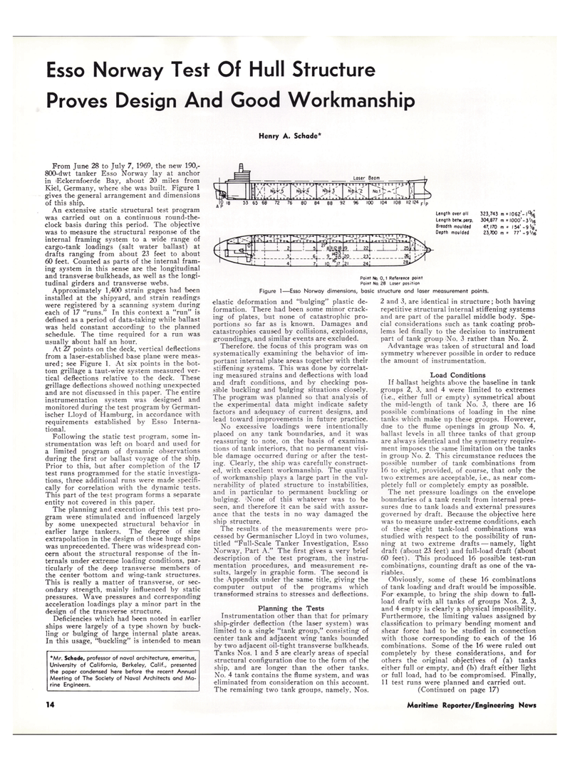
Length over oil
Length befw. perp.
Breodth moulded
Depth moulded 323,743 304,877 47,170 23,700 m = l062'-l'^ m = IOOO'-3 m - 154' - 9 '/e" m = 77'-9'/|6
Figure 1-
Point No. 0,1 Reference point
Point No. 28 Laser position -Esso Norway dimensions, basic structure and laser measurement points.
From June 28 to July 7, 1969, the new 190,- 800-dwt tanker Esso Norway lay at anchor in Eckernfoerde Bay, about 20 miles from
Kiel, Germany, where she was built. Figure 1 gives the general arrangement and dimensions of this ship.
An extensive static structural test program was carried out on a continuous round-the- clock basis during this period. The objective was to measure the structural response of the internal framing system to a wide range of cargo-tank loadings (salt water ballast) at drafts ranging from about 23 feet to about 60 feet. Counted as parts of the internal fram- ing system in this sense are the longitudinal and transverse ibulkheads, as well as the longi- tudinal girders and transverse webs.
Approximately 1,400 strain gages had been installed at the shipyard, and strain readings were registered by a scanning system during each of 17 "runs." In this context a "run" is defined as a period of data-taking while ballast was held constant according to the planned schedule. The time required for a run was usually about half an hour.
At 27 points on the deck, vertical deflections from a laser-established base plane were meas- ured; see Figure 1. At six points in the bot- tom grillage a taut-wire system measured ver- tical deflections relative to the deck. These grillage deflections showed nothing unexpected and are not discussed in this paper. The entire instrumentation system was designed and monitored during the test program by German- ischer Lloyd of Hamburg, in accordance with requirements established by Esso Interna- tional.
Following the static test program, some in- strumentation was left on board and used for a limited program of dynamic observations during the first or ballast voyage of the ship.
Prior to this, but after completion of the 17 test runs programmed for the static investiga- tions, three additional runs were made specifi- cally for correlation with the dynamic tests.
This part -of the test program forms a separate entity not covered in this paper.
The planning and execution of this test pro- gram were stimulated and influenced largely by some unexpected structural behavior in earlier large tankers. The degree of size extrapolation in the design of these huge ships was unprecedented. There was widespread con- cern about the structural response of the in- ternals under extreme loading conditions, par- ticularly of the deep transverse members of the center 'bottom and wing-tank structures.
This is really a matter of transverse, or sec- ondary strength, mainly influenced by static pressures. Wave pressures and corresponding acceleration loadings play a minor part in the design of the transverse structure.
Deficiencies which had been noted in earlier ships were largely of a type shown by buck- ling or bulging of large internal plate areas.
In this usage, "buckling" is intended to mean *Mr. Schade, professor of naval architecture, emeritus,
University of California, Berkeley, Calif., presented the paper condensed here before the recent Annual
Meeting of The Society of Naval Architects and Ma- rine Engineers. elastic deformation and "bulging" plastic de- formation. There had been some minor crack- ing of plates, but none of catastrophic pro- portions so far as is known. Damages and catastrophies caused by collisions, explosions, groundings, and similar events are excluded.
Therefore, the focus of this program was on systematically examining the behavior of im- portant internal plate areas together with their stiffening systems. This was done by correlat- ing measured strains and deflections with load and draft conditions, and by checking pos- sible buckling and bulging situations closely.
The program was planned so that analysis of the experimental data might indicate safety factors and adequacy of current designs, and lead toward improvements in future practice.
No excessive loadings were intentionally placed on any tank boundaries, and it was reassuring to note, on the basis of examina- tions of tank interiors, that no permanent visi- ble damage occurred during or after the test- ing. Clearly, the ship was carefully construct- ed, with excellent workmanship. The quality of workmanship plays a large part in the vul- nerability of plated structure to instabilities, and in particular to permanent buckling or bulging. iNone of this whatever was to be seen, and therefore it can be said with assur- ance that the tests in no way damaged the ship structure.
The results of the measurements were pro- cessed by Germanischer Lloyd in two volumes, titled "Full-Scale Tanker Investigation, Esso
Norway, Part A." The first gives a very brief description of the test program, the instru- mentation procedures, and measurement re- sults, largely in graphic form. The second is the Appendix under the same title, giving the computer output of the programs which trans-formed strains to stresses and deflections.
Planning the Tests
Instrumentation other than that for primary ship-girder deflection (the laser system) was limited to a single "tank group," consisting of center tank and adjacent wing tanks bounded by two adjacent oil-tight transverse bulkheads.
Tanks Nos. 1 and 5 are clearly areas of special structural configuration due to the form of the ship, and are longer than the other tanks.
No. 4 tank contains the flume system, and was eliminated from consideration on this account.
The remaining two tank groups, namely. Nos. 2 and 3, are identical in structure; both having repetitive structural internal stiffening systems and are part of the parallel middle body. Spe- cial considerations such as tank coating prob- lems led finally to the decision to instrument part of tank group >No. 3 rather than No. 2.
Advantage was taken of structural and load symmetry wherever possible in order to reduce the amount of instrumentation.
Load Conditions
If ballast heights above the baseline in tank groups 2, 3, and 4 were limited to extremes (i.e., either full or empty) symmetrical about the mid-length of tank No. 3, there are 16 possible combinations of loading in the nine tanks which make up these groups. However, due to the flume openings in group No. 4, ballast levels in all three tanks of that group are always identical and the symmetry require- ment imposes the same limitation on the tanks in group No. 2. This circumstance reduces the possible number of tank combinations from 16 to eight, provided, of course, that only the two extremes are acceptable, i.e., as near com- pletely full or completely empty as possible.
The net pressure loadings on the envelope boundaries of a tank result from internal pres- sures due to tank loads and external pressures governed by draft. Because the objective here was to measure under extreme conditions, each of these eight tank-load combinations was studied with respect to the possibility of run- ning at two extreme drafts — namely, light draft (about 23 feet) and full-load draft (about 60 feet). This produced 16 possible test-run combinations, counting draft as one of the va- riables.
Obviously, some of these 16 combinations of tank loading and draft would be impossible.
For example, to bring the ship down to full- load draft with all tanks of groups Nos. 2, 3, and 4 empty is clearly a physical impossibility.
Furthermore, the limiting values assigned by classification to primary bending moment and shear force had to be studied in connection with those corresponding to each of the 16 combinations. Some of the 16 were ruled out completely by these considerations, and for others the original objectives of (a) tanks either full or empty, and (b) draft either light or full load, had to be compromised. Finally, 11 test runs were planned and carried out. (Continued on page 17) 14 Maritime Reporter/Engineering News

 10
10

 12
12
